Need Help with First Tube Build - WE91 300B Parafeed Derivative

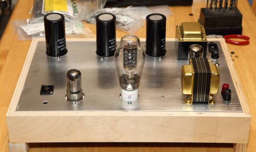
Just one or two more parts to source and I think I'll have everything I need for a full prototype build on an aluminum plate (though, I'm sure I've left *something* out and will have to wait for yet another order to arrive).

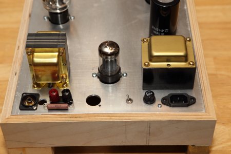
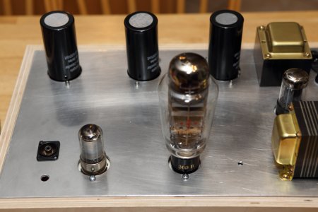
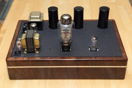
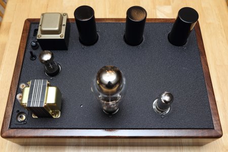
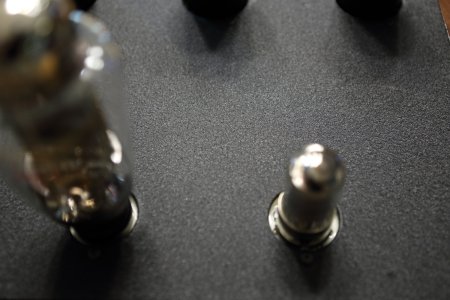
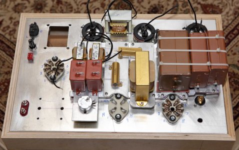
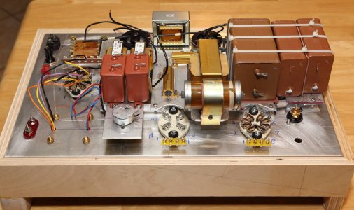
Everything is now attached to the base plate except the power and output transformers and I still need to come up with a way to mount the coupling cap between the signal tubes.  I'll probably create some sort of metal clamp with a rubber liner and connect it to the mounting screw for the 300B plate choke.

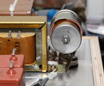
I did a little prep work on the PGP transformer.  I gently sanded the laminations and painted it with a gloss black enamel and painted the bell end to make it look like a brass finish.  I'll post an image of the transformer when the paint dry.  Almost ready to start the wiring. 
 

Attachments

  • IMG_1646.JPG
    IMG_1646.JPG
    308.5 KB · Views: 58
Yep!  My choice of caps ate up a fair amount of real estate under the hood.  Without these, I think the chassis could have been half this size...  I'll need to clear some space on the audio rack for sure!
 
I managed to fashion a custom clamp for the coupling capacitor out of a chassis clamp for a larger film cap.  It may not be super elegant, but it's functional and holds the cap securely.  In the few minutes of spare time I have each day, I think I'm ready to start the wire layout to see how things go. 

I finally found the shoulder washers I need to isolate the power transformer when I mount it.  Is there any value to adding a neoprene washer to the mix for this transformer (for vibration isolation), or should I just stick with the shoulder washers for electrical isolation?
 

Attachments

  • Coupling Cap.JPG
    Coupling Cap.JPG
    269 KB · Views: 30
Good to know, Paul - thank you.  I have experience with n=1 of Mike's power transformers so far.  I've been through lots of transformers in the past, some from the same manufacturer where one example buzzes/vibrates but the next one doesn't, so I've learned to be a little cautious. 

Is there any reason to electrically isolate any of the other iron from the chassis and ground it separately with a solder tab and wire, or should I just bolt it all to the metal chassis and not think about any more?
 
We do that with all of the chokes and transformers on our products, but I haven't ever seen anybody else in the industry that does. 
 
I'm in the process of wiring up the prototype to see what changes might be necessary before I begin a final build with powder coated plates.  I managed to find some rubber grommets for where the output transformer wiring passes through the top plate.  I also need to get some longer mounting bolts for the PGP transformer.  After adding in the shoulder washers and the thickness of the top plate, there's no exposed threads for the nuts. 

Is it OK to use a zip tie to bundle up the remaining wires from the output transformer after putting some shrink wrap over the ends?
 

Attachments

  • Top Side.JPG
    Top Side.JPG
    127.3 KB · Views: 34
  • Under the Hood.JPG
    Under the Hood.JPG
    161.8 KB · Views: 37
Yeah, I find for MQ iron that slipping a little heatshrink over the exposed wires and then wrapping them into a loop that you can secure with a ziptie keeps them out of the way.
 
Thanks, Paul.  I was thinking this was the case, but didn't want to cause some bizarre interaction effect from stray wires floating around or bundled where they shouldn't be...
 
Managed to find a spare few hours over the past couple of days to finish my aluminum-plate prototype.  I used color coded wire and tried to make things more neat than my plywood prototype was.  The result is that the new one works, but produces about 39mV of AC hum at the speaker terminal, which is audible at the speaker.  Ironically, the one with flying wires is still nice an quiet.

Need to move some wires around to solve the hum problem.  My first guess is that it's from driver filament AC passing by the plate coke for the 300B...  Need to drill some holes in my support structure and pass wires under the platform so they are better separated.  I didn't take wire paths into account with my physical layout.   

Green is AC heater wire, red is B+, black is ground, and yellow is signal wire. 
 

Attachments

  • IMG_4317.JPG
    IMG_4317.JPG
    175.3 KB · Views: 40
  • IMG_4318.JPG
    IMG_4318.JPG
    165.7 KB · Views: 27
Hello,
The twisted green pair of heater wires passing close and parallel to the power switch and fuse holder could be problematic.
Looking at the photo I would just try to bend / flip those toward the 2 Hammond 155 chokes. Also it is preferred to keep heater / filament leads as close to the chassis as possible and use the perimeter of the chassis for said wiring.
Give it a try, it will only take a few seconds to get those wires away from the AC input.
Best wishes, Good luck and Good job.
 
Thanks, Lee.  I'll give it a try.  The twisted pair for the rectifier heater is arranged closer to the 120v mains because I figured it would create trouble if I tipped it toward the 155B chokes which are for the 300B heater.  I'll try this first.  If this doesn't do it, I think I'll play with the AC heater wire path for the driver tube.
 
Lee:  I moved the AC heater wires for the rectifier further away from the 120vAC mains as you suggested.  They are now parallel to the HV secondary for the B+.  This reduced the ripple on the speaker output from ~39mV AC down to somewhere closer to 5mV!  What difference this made!  I didn't consider that AC would interfere with AC - I was trying to keep it away from DC supplies.

Paul: before grounding the chassis plate as you suggested, I measured it with respect to ground and found 22v AC on the plate!  Yikes :o  
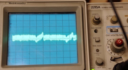
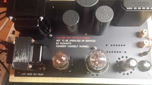
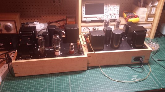
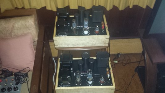
Grounding the top plate took the ripple on the speaker output down to the level I have in my wooden prototype of about 0.5mV AC.  This seems to wander around a bit from 1mV to 0.2mV with no particular pattern.  Either way, it is now at a level that I can't hear at the speaker, so I don't care anymore.   

All of the other measures are great so far, the AC heater for the input tube is 6.4v, I have 5.15vDC on the 300B heater, and about 5.10vAC on the rectifier heater.  B+ is about 422v and the supply for the input tube reads about 167v.  All of these are within ~2-3% of target with 125v AC mains (pretty much normal all year 'round where I live), so I'm pretty happy with this!  My main goal was to verify the layout and the wiring wouldn't cause problems when switching to a more appropriate long-term chassis. 

The next step is to start drilling and cutting plates for the final implementation and get them powder coated (when things open up again, that is).

The empty hole in the chassis plate was intended for a volume pot.  Not sure if I actually want to implement this, or just make it a dedicated amp and use a preamp for volume control. 

Thanks for the help guys!  I hope everyone is well!
 
After a long time not being able to work on my amp, I have been able to make some progress again.  I was experimenting with positioning the RCA input next to the input tube (away from the AC mains input and speaker output) vs putting the RCA input next to the output transformer and speaker output terminals.  There is very minimal difference in speaker output noise levels, both measure mostly less than 1.0mV AC noise on my DMM.

I think I prefer having all of the inputs/outputs in a line along a single edge of the amp because it makes routing wires in and out of the amp visually more neat on the equipment rack.  Is there any reason that I should not do this? 

With either RCA input placement, the amp sounds VERY quiet on my Tang Band 1772 speakers (advertised sensitive of 95dB - this is probably optimistic after my correction network to tame the treble).  I have attached an image of each RCA input configuration, as well as an image of the output noise level on my scope with the RCA input "open" (not shorted).  The scope is set to display 5mV per division on the y-axis with a time window of 2ms per division on the x-axis.

Thanks for any insights.


Attachments

  • Long Input RCA open with cap 2msDiv1.JPG
    Long Input RCA open with cap 2msDiv1.JPG
    275.7 KB · Views: 20
  • Input Next to Output.JPG
    Input Next to Output.JPG
    326 KB · Views: 33
  • Input Next to Tube.JPG
    Input Next to Tube.JPG
    291.9 KB · Views: 31
You shouldn't have any problems with the input and output next to each other.
I did this on a pair of 300b mono's that I built a while back.
 

Attachments

  • 20190528_124725.jpg
    20190528_124725.jpg
    856.3 KB · Views: 35
  • 20190528_124747.jpg
    20190528_124747.jpg
    987.2 KB · Views: 28
  • 20190808_002751.jpg
    20190808_002751.jpg
    982.7 KB · Views: 28
Thanks, Lee.  I've been playing around with the prototype top plate and I'm happy enough to drill holes anywhere, but I'm becoming a bit more conservative as I'm thinking about the work required to make two final plates and get them powder coated.
 
Work and projects around the house have been keeping me pretty busy lately, so my progress has still been slow.  But, I'm coming down the home stretch.  Got my aluminum back from the powder coating shop last week and thought it turned out very nice.  I went with a textured black (thanks for the suggestion, PB!) with speckles of gold in it for the base plate and a gold-ish color for the power transformer bells in an effort to come close to the brass bells of the output transformer.  Both were a dual-layer powder coat process.  I also stripped the shrink wrap from the PSU caps and painted them with a gloss black enamel so they wouldn't have silver circles on top of them.

I had an interesting problem with the aluminum plates.  The sheets that I received from the shop were slightly bowed, so I took them back and asked them to run the sheets through their rollers to flatten them out.  A few minutes later, I had nice flat sheets in my hands.  But when I picked them up from the powder coat shop, the bow had returned - I guess the heat from the powder coating process caused them to spring again.  Thus, there is a slight bow to the top plate that flattens out a little with the weight of all of the components on the plate.  Guess I could always mount an "L" bracket to the inside of the wooden chassis and drive a screw through the top plate into the L to pull it flat again.  I think I'll leave it alone for now...

I've attached a few images of the top of the amp.  I haven't finished the wiring yet, so the amp won't be functional for another few days.   
 

Attachments

  • Finished Appearance.JPG
    Finished Appearance.JPG
    186.9 KB · Views: 45
  • Top View.JPG
    Top View.JPG
    582.7 KB · Views: 22
  • Plate Texture.JPG
    Plate Texture.JPG
    405.6 KB · Views: 17
Back
Top