The bow will go away over time and comes from the production of the sheets themselves.
You are using an out of date browser. It may not display this or other websites correctly.
You should upgrade or use an alternative browser.
You should upgrade or use an alternative browser.
Need Help with First Tube Build - WE91 300B Parafeed Derivative
- Thread starter EricS
- Start date
D
Deke609
Guest
Eric - It looks amazing! Nicely done. Happy to see a new post about your progress. Looking forward to the finish and listening impressions.
cheers, Derek
cheers, Derek
Thermioniclife
Member
Nice job Eric, Sweet inlay and finish. Something to be proud of.
EricS
Member
As I'm nearing completion, I have a question about using/setting the hum pot in this design. My DC filament supply for the 300B is a CLCR (4,700uF, Hammond 155B, 10,000uF, 0R5 10W). The hum pot is a 15R 5w pot flanked by 22R 5w resistors. AC ripple on the 300B heater is essentially not measurable on my DMM (0.0mV). As a result, adjusting the hum pot makes no audible difference at the speaker output (I'm using Tang Band 1772 drivers right now somewhere near 92-93dB efficiency after I tame the treble).
Given that I can't *hear* any difference, where should I set the pot for best/safest operation? Should I just leave it in the middle of the range?
Thanks for any insights!
Given that I can't *hear* any difference, where should I set the pot for best/safest operation? Should I just leave it in the middle of the range?
Thanks for any insights!
I would just put it in the middle. You may be able to measure a null with a scope or FFT, but if you can't hear it I wouldn't bother!
EricS
Member
Happy New Year!
Wow - I didn't realize it's been since July that I've worked on my amps! The fall semester kept me pretty busy, but now I've got just a little bit of time on my hands again and I'm hoping to get these amps finalized.
I may have made a mistake in the context of my mental health, but I recently picked up a nice USB Analog to Digital Converter so I could more easily do some sound/noise measurements. Maybe there is something to that old "ignorance is bliss" sort of thing ;-)
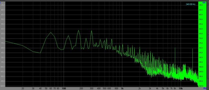
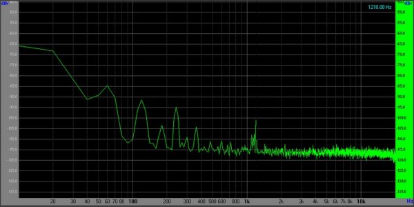
Anyhow, I measured the noise floor for my prototype amp. The graph below is what I am measuring with the input shorted and an 8R load on the output. Removing the input shorting cap at the RCA in makes no difference in the noise profile. But, since I have no context, I'm wondering what the noise floor "should" look like for an amp like this. Is this a good result, or do I still have some work to do?
To me, it looks like I have some power supply noise to deal with, as evidenced by the peaks at 60Hz, 120Hz, 180Hz, 240Hz, and 300Hz. The odd harmonics seem to be a bit higher in magnitude than the even harmonics. Measurements at the speaker terminal indicate about 42mVDC offset and 1.3mVAC hum. The noise floor on the ADC all by itself is about -120dB.
Any input would be appreciated!
Wow - I didn't realize it's been since July that I've worked on my amps! The fall semester kept me pretty busy, but now I've got just a little bit of time on my hands again and I'm hoping to get these amps finalized.
I may have made a mistake in the context of my mental health, but I recently picked up a nice USB Analog to Digital Converter so I could more easily do some sound/noise measurements. Maybe there is something to that old "ignorance is bliss" sort of thing ;-)
Anyhow, I measured the noise floor for my prototype amp. The graph below is what I am measuring with the input shorted and an 8R load on the output. Removing the input shorting cap at the RCA in makes no difference in the noise profile. But, since I have no context, I'm wondering what the noise floor "should" look like for an amp like this. Is this a good result, or do I still have some work to do?
To me, it looks like I have some power supply noise to deal with, as evidenced by the peaks at 60Hz, 120Hz, 180Hz, 240Hz, and 300Hz. The odd harmonics seem to be a bit higher in magnitude than the even harmonics. Measurements at the speaker terminal indicate about 42mVDC offset and 1.3mVAC hum. The noise floor on the ADC all by itself is about -120dB.
Any input would be appreciated!
Attachments
1.3mV of hum would be OK with me. That's not quite as low as it could be with a DC supply, but about 10dB quieter than an AC heated amp.
The FFT image you posted is useful in some ways, but not necessarily as useful as knowing the actual voltage.
Incidentally you have two power supplies that will make 120Hz noise, not 60Hz noise. The 60Hz noise you're seeing could be a ground loop issue or magnetic coupling between the PT and your output iron.
D
Deke609
Guest
Hey Eric! Welcome back! I was wondering what happened to you and this amp.
Could some of that noise be residual power supply ripple appearing at 300B grid via the plate of the driver tube? If so, maybe consider a cascode constant source as driver load?
just a thought.
cheers, Derek
Could some of that noise be residual power supply ripple appearing at 300B grid via the plate of the driver tube? If so, maybe consider a cascode constant source as driver load?
just a thought.
cheers, Derek
EricS
Member
Paul: Seems like I'm in "the ballpark" of measurements. What specific voltage measures would be more indicative of what is going on here? Are you talking about ripple voltage at the plates of the input and output tubes? Or filament voltage on the 300B? Is it safe to just put my DMM from plate to ground for a ripple measurement?
Derek: I didn't realize it had been so long! The fall semester seemed to bring about 10M zoom meetings (waaaay more than my "normal" number of meetings during a semester). The past few weeks have been spent catching up on things that got put off over the past few months. Almost caught up now ;-) I'm really looking forward to wrapping this project up while I have a little bit of time!
Derek: I didn't realize it had been so long! The fall semester seemed to bring about 10M zoom meetings (waaaay more than my "normal" number of meetings during a semester). The past few weeks have been spent catching up on things that got put off over the past few months. Almost caught up now ;-) I'm really looking forward to wrapping this project up while I have a little bit of time!
Your FFT measurement shows 60Hz. Your power supply ripple frequency would be 120Hz (on the B+ and the filament supply), ergo you do not have an issue with power supply ripple, you have either magnetic coupling between the power transformer and signal handling iron, or some kind of ground loop.
EricS
Member
I solved my problem after poking around for most of the day today! ") With Paul's guidance (thank you, Paul!) on ground-related issues, I took a more methodical approach today when I noticed something very strange. The noise profile I was seeing was present even with the amp turned off! Turns out, just having it plugged in was causing all of the noise I was seeing in the FFT graph see first image - "Power Off- Plugged In- No Cheater"
With Paul's guidance (thank you, Paul!) on ground-related issues, I took a more methodical approach today when I noticed something very strange. The noise profile I was seeing was present even with the amp turned off! Turns out, just having it plugged in was causing all of the noise I was seeing in the FFT graph see first image - "Power Off- Plugged In- No Cheater"
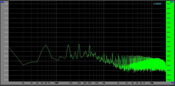
With Paul's hint of a grounding issue, I pulled the plug from the wall and inserted a "cheater plug" that has no ground lug on it, and plugged it back in. The amp was still off, but the noise floor dropped all of the way down to -115dB (except a little peak at 60Hz). See the second image "Power Off - Plugged In - Cheater Plug"
Since I wasn't really excited to run an amp with a 450v power supply without a ground connection, I tried something else. I inserted a CL-60 thermistor between the AC Ground/Chassis Ground and the PSU/signal ground. So the aluminum plate is still directly bonded to mains earth, but the rest of the audio ground is separated by the thermistor. It measures about 15R when cold and can handle more than 5A of current, so I figure it's plenty robust for this application, especially since the amp itself is protected by a 1.25A fuse. This way, any potential fault will still find its way to mains earth for safety, but the signal ground is a bit isolated.
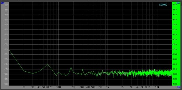
So, the final image here is my noise floor with the amp powered up with the CL-60 thermistor in place. See "Power On - With CL60."
Playing with the hum pot impacts the 120Hz and 240Hz peaks. By adjusting the pot, I was able to reduce the 120Hz peak from -66dB down to -80dB. At the same time, the 240Hz peak went from -83dB down to -92dB. This is easy to see in the FFT, though is just *barely* audible through headphones. The amp is now *VERY* quiet. The overall AC hum at the speaker terminals is now about 0.65mVAC - less than half of what it was before! With a little more tweaking tomorrow, I think I can get these two peaks down just a bit more. I can't seem to do anything with the 60Hz peak, though. It pops up as soon as the switch is turned on.
I am just thrilled with this amp now! Now that I've solved this issue, it's time to rebuild the second amp on my power coated aluminum base.
With Paul's guidance (thank you, Paul!) on ground-related issues, I took a more methodical approach today when I noticed something very strange. The noise profile I was seeing was present even with the amp turned off! Turns out, just having it plugged in was causing all of the noise I was seeing in the FFT graph see first image - "Power Off- Plugged In- No Cheater"With Paul's hint of a grounding issue, I pulled the plug from the wall and inserted a "cheater plug" that has no ground lug on it, and plugged it back in. The amp was still off, but the noise floor dropped all of the way down to -115dB (except a little peak at 60Hz). See the second image "Power Off - Plugged In - Cheater Plug"
Since I wasn't really excited to run an amp with a 450v power supply without a ground connection, I tried something else. I inserted a CL-60 thermistor between the AC Ground/Chassis Ground and the PSU/signal ground. So the aluminum plate is still directly bonded to mains earth, but the rest of the audio ground is separated by the thermistor. It measures about 15R when cold and can handle more than 5A of current, so I figure it's plenty robust for this application, especially since the amp itself is protected by a 1.25A fuse. This way, any potential fault will still find its way to mains earth for safety, but the signal ground is a bit isolated.
So, the final image here is my noise floor with the amp powered up with the CL-60 thermistor in place. See "Power On - With CL60."
Playing with the hum pot impacts the 120Hz and 240Hz peaks. By adjusting the pot, I was able to reduce the 120Hz peak from -66dB down to -80dB. At the same time, the 240Hz peak went from -83dB down to -92dB. This is easy to see in the FFT, though is just *barely* audible through headphones. The amp is now *VERY* quiet. The overall AC hum at the speaker terminals is now about 0.65mVAC - less than half of what it was before! With a little more tweaking tomorrow, I think I can get these two peaks down just a bit more. I can't seem to do anything with the 60Hz peak, though. It pops up as soon as the switch is turned on.
I am just thrilled with this amp now! Now that I've solved this issue, it's time to rebuild the second amp on my power coated aluminum base.
Attachments
EricS
Member
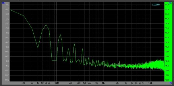
I have completed my second amp on the finished chassis and tried a different grounding scheme. With my first monoblock, I directly grounded the aluminum plate to AC mains earth and separated the rest of the PSU and audio ground with a CL-60 thermistor. In the second monoblock, I put the CL-60 right at the IEC connector, so the *entire* amp is isolated from AC mains earth right from the start. This lowered the noise floor even further. The CL-60 measures about 15R. As an experiment, I substituted in a different type of thermistor that measures closer to 26R and this just raised the noise floor again, so I went back to the original one.
The result is a 15dB reduction in noise at 60Hz, a 9dB reduction at 120Hz, a 4dB reduction at 240Hz, and an 8dB reduction at 360Hz. The overall noise floor from about 500Hz to 20kHz is also about 5dB lower as well. They are darn near "dead silent" with my headphones plugged into my FocusRite analog to digital converter. Not really sure what that little spike is near 1kHz - seems to be related to a tube or two settling in - it was there when I made my screen cap, but isn't there now. It's interesting to hear the metal in the tubes creaking and expanding while listening through headphones as the amp warms up.
At this point, I'm willing to call them done! Pfew - my first purchase for this set of amps was in Dec of 2016. I'm listening to stereo music through them right now for the first time and they sound just great! Oh the glory!
I'll post of picture of the new twins after I've had some time to listen to them...
A deep and heartfelt "Thank You!" for everyone's help and input (and patience with me) along the way. Special thanks and appreciation to Paul Joppa for the excellent circuit and to Paul Birkeland for the construction help! I couldn't have pulled off my first tube build without all of the guidance!
Edited to fix my usual typos...
Attachments
Thermioniclife
Member
That's interesting, I have used ntc thermistors in the past with varying degrees of success but I always used them on the hot mains input. Does it get hot in the audio ground as it would inline with the mains hot lead?
There isn't any current flowing, so there will be no heat. It will definitely get hot if there's a fault in the amp though.
Thermioniclife
Member
Thats what I thought but how does it lessen hum. would a resistor of equal value as the ntc in a cold state do the same thing?
Yes. The issue with a resistor alone lies in the fault condition, where drawing a lot of current across the resistor just develops a lot of voltage across it and may not be sufficient to blow a breaker. That's why in our products we use a resistor with a pair of antiphase diodes across it. The diodes limit the possible voltage drop in case things go really wrong. An NTC thermistor will also drop in resistance significantly if you try to pull much current through it, though I would expect the diodes to work more quickly.Thermioniclife said:would a resistor of equal value as the ntc in a cold state do the same thing?
Thermioniclife
Member
on which products do you use a resistor and antiphase diodes on the audio ground? I have a Crack, C2a, Mainline, S3x and BeePre.
Moreplay and BeePre 2 have it. It will get built into the rest of the heapdhone amps and preamps down the road as the kits get refreshed.
Similar threads
- Replies
- 2
- Views
- 307
- Replies
- 45
- Views
- 1K