Need Help with First Tube Build - WE91 300B Parafeed Derivative

Thanks for this sanity check, Paul and Derek!  I've never come across that before.  Sounds like it's time to stop tilting at this windmill and just enjoy listening  :)

Here is a set of final measurements I made of filament voltages for both amps.  I used my variac to adjust AC mains from 120v to 125v (typical range for my neighborhood seems to be low-122-ish to high-123-ish.  Excuse me while I cue up some of my favorite vinyl!


Attachments

  • Final Filament Voltages.jpg
    Final Filament Voltages.jpg
    75.8 KB · Views: 17
Deke609 said:

Interesting read - never heard about this before.  It also looks like a pretty sophisticated circuit/approach to a solution...  I think I'll pass and just learn to live with the noise that I can't hear  8)

This is making me think there is nothing wrong with my FocusRite ADC.  I suppose the audio system in my new computer has some software/circuitry to mitigate 1/f noise.

 
EricS said:
Thanks for this sanity check, Paul and Derek! ...

Any sanity here is not my doing. I'm just a grinning fool trying to clap along to PJ's beat.  ;D 

Enjoy the vinyl listening! [Now where's a clapping monkey emoji when you need one?]

cheers, Derek
 
Since this project is "mostly" wrapped up (isn't there ALWAYS a tweaking phase?!?), I thought I'd share my final parts list and schematic as implemented.  It's a joy to listen to, but I have to say that half of the fun is in gathering the parts, as Jamie suggested. 

Time to find my next project, though I already have 4 amps that don't fit on my oversized equipment rack... 
 

Attachments

Eric - Thanks for sharing the project. It's been fun to follow along.

I checked out your parts and prices list. Substracting the price of the EML 300Bs, that's $2200 for a beautiful pair of well-designed (and no doubt great sounding) parafeed monoblocks with really nice components. Quite a deal! (Although it looks like you got your MQ iron at a steal - including from Mike!).

Looking forward to reading the build-log of your next project!

cheers, Derek
 
Its funny, after playing around in the tube domain for a little while, I am inclined to agree that this is a bargain for a great pair of 300B monoblock amps.  At the start of this project, though, it was a bit of sticker shock for me.  I have built a number of solid state Class-A amps and the price tag on these has ranged from a low of < $100 (built with recycled/scavanged parts) to a high of about $600 for a premium-parts build.   
 
I've been enjoying my new 300B monoblock amps for a little while now and wanted to confirm an operational detail.  After several hours of operation, the PGP 8.1 power transformer is running pretty warm.  I can measure close to 73 or 75c. 

Is this temperature level normal and/or OK?  Transformers in my solid state stuff run much cooler.
Thanks,
Eric
 
That's pretty warm, all right. I assume this is surface temperature?

Can  you check the cathode voltage (wiper of the hum pot) - and what is the cathode resistor value? If it's operating correctly, it should be within the spec of the transformer, but it's an old design and I don't know what the expected surface temperature is. In modern practice, you'd like to stay below 60C.

Thinking a little  more - what is your powerline voltage? B+ volts? The transformer was originally intended for 117 volts, IIRC - I'll check my notes.

How is the ventilation?
 
Yes, this is surface temperature for the power transformer measured with an infrared non-contact thermometer.  Temp measures cooler closer to the top (in the mid 60s), warmer down by the top plate (low 70s). 

300B cathode resistor is 1k 50w aluminum body wire wound.  Last time I measured cathode voltage, it was about 68v.  It has never measured more than 70vDC.  B+ is about 420vDC measured from plate to ground.  The 300B dissipates about 23-24w.  All of this seems pretty much right on spec to me.  Each monoblock draws about 0.75A or about 93w.  AC mains is fused with a 1.25A slow-blow.

My AC mains tend to range between 122-125vAC.  If the transformer is intended for 117v, this is likely why I had to add voltage trimming resistors to all of my heater circuits.

My chassis doesn't have very much ventilation.  The chassis is wood all around the base, it sits on a few felt pads that are maybe 1/8" thick.  The aluminum top plate does not have any vent holes in it.  The power transformer sits on top of nylon shoulder washers, so there is a small gap between the laminate stack and the base plate for the transformer - maybe 1/16".  It was on for about 6-7 hours when I measured temperatures.
 
Hmmm...  I added 1R0 to the secondary for the 300B heater, 1R5 to the secondary for the input tube heater, and 0R1 to the secondary for the rectifier heater. 

Would a better approach be to add some resistance to the primary of the power transformer?  Perhaps a CL-60 of one variety or another might bring the primary voltage down a bit.  Seems like a 10R CL-60 might drop 5-7v off the primary.

I would certainly welcome other ideas for trimming primary voltage.  I'd like to avoid cooking the power transformers...
 
I found the spec sheet (from Freed):

DocB is right, it was wound for 117 volts input; it would be prudent to take 5 to 8 volts off of that; you could likely take those resistors out of the filament/heater lines then. Personally, I'd do it with a homemade autoformer stepdown in its own box, since it would generate less heat than a resistor.  You can make one with a 6.3v 2A or greater filament transformer, which should handle both amps.

Temperature rise is specified as 45 to 50 degrees. If room temperature is 20C (68F), that's 65-70C at the transformer, so it's operating within spec though at the limit. For what it's worth, we used it in the pld B-Glow and ParaBee at 70mA and never had any issues.

More ventilation would help, especially getting a little airflow over the 1K cathode resistor. I'd start with 3/8 or 1/2 inch clearance at the bottom - it's easiest.

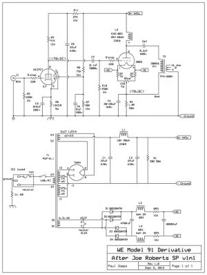
What are you using for a rectifier? The 5v winding is rated 2.0 amps, which is why I specified a 5AR4 rather than the usual 5U4. Actually, the spec sheet suggests a 5Y3, which would give you a bit less B+ but would be easier on the transformer. Other possibilities are 5R4 or 5V4.

It is considered normal to take 3-4 hours for the power transformer to come to final temperature.
 
Thanks, Paul, this is very helpful!  An outboard autoformer sounds like an easy solution and I'll likely be able to remove some of my filament trimming resistors.  The irony is that it took me a while to dial in those voltage levels to my ac mains ;-)

I'm running a NOS Mullard 5AR4 f31 rectifier - probably from the late 1950s or early 1960s or so.  I'll see if I can find some nice looking feet for the chassis - this should help a little as well.

Now that I have these working, it would be a shame to over cook things...
 
I always hesitate a bit when asking questions that reveal my lack of knowledge, but here it goes anyhow:    ???

Lowering voltage on the primary will certainly lower voltages on the secondaries, include B+ which I expect will decrease from ~420vDC to somewhere near ~400vDC (I'm expecting an approx 5-6% decrease in voltages across the board).  How will this impact the bias point of the 300B tube?  Will it draw more current at the lower voltage point in order to maintain its "desired" operating point of about 23w? Or will I need to tweak something else?

Thanks!
 
The cathode resistor will stabilize the bias, reducing it in rough proportion to the voltage change. In the old days it was called "automatic bias" or "self bias" for that reason. Nothing needs to be changed for less than +/- 30% voltage changes.

A way to visualize this (that works for me - YMMV!): If the plate voltage drops, the current will drop, reducing the bias voltage which increases the current.

It's a form of "negative feedback", effective at DC but not audio because of the bypass capacitor. You could call it "passive servo bias" as well. Don't you love it when something simple has several different names to confuse the unwary?
 
You can draw the load line for the cathode resistor on a set of 300B curves knowing that you have a 1K resistor, you can go to the 100V grid bias line and put a dot at 100mA, then another dot at 50V grid bias and 50mA, then connect the two with a line.  Your amp will always operate on that line, so you can find the spot that's a little under 400V (you'll lose some voltage across your plate choke) and see what current should be drawn through the amp. 

The bucking transformer is indeed a good idea and a 6.3V 1A transformer would do that job nicely per amp, or a shared 6.3V/2A unit for both.
 
PJ: Thanks for the explanation.  I've read a little bit about self bias circuits and was wondering if this change would sort itself out. 

PB: Thanks also for the explanation using the load line graphs.  This is an area of understanding tube amps that I haven't invested the necessary time to understand, so I appreciate the primer you've provided.

Seems like I have a whole new round of experimentation ahead with a bucking transformer and re-tweaking my filament supplies.  I think the best place to start might be with my variac to see what happens when the mains voltage is dropped by 6 or 7 volts. 

Thought I was done with tweaking for a while  ;D
 
I've been poking around looking for a suitable filament transformer for bucking use.

Found a Hammond P-T166M6 (link is here https://www.hammfg.com/electronics/transformers/power/166) that is rated at 117V primary, 6.3v center tapped secondary rated at 3A, with an 18.9VA overall rating.  At first glance, this seems appropriate to me (6.3v 3A secondary), but the overall rating is only 18.9VA which seems small to me.  Does the transformer itself need a rating that is closer to 200VA if it's going to power two amps that each draw close to 100w from the AC mains?

Or, should I choose a 12v or 12.6v secondary and only use half of the secondary winding instead of using both as I would with a 6.3v center tapped secondary?

Thanks for the guidance!
Eric
 
The transformer is not handling the full power; only the 6v winding carries any load current. So it does not nee to have a large VA rating. A 3A secondary can handle 3A of load current.
 
Back
Top