You may find that you still blow the 1A fuses occasionally. You could just toss a 3A fast in there instead. It will allow things to get a little crispier if there's a fault, but it will still blow. You could also look at using an NTC thermistor to mellow out the startup surge.
You are using an out of date browser. It may not display this or other websites correctly.
You should upgrade or use an alternative browser.
You should upgrade or use an alternative browser.
Need Help with First Tube Build - WE91 300B Parafeed Derivative
- Thread starter EricS
- Start date
EricS
Member
Just measured total current draw for the first time (duh...). I pulled the fuse and put my meter across the terminals.
Power on surge: 0.52A (64w)
Drops to 0.34A (42w) after the filaments are warm
Steady State 0.76A (93w) after B+ is up, so a 500mA fuse was definitely too small.
Paul, you are right (as usual!) - it just might open a 1A fast-acting fuse from time to time.
Power on surge: 0.52A (64w)
Drops to 0.34A (42w) after the filaments are warm
Steady State 0.76A (93w) after B+ is up, so a 500mA fuse was definitely too small.
Paul, you are right (as usual!) - it just might open a 1A fast-acting fuse from time to time.
EricS
Member
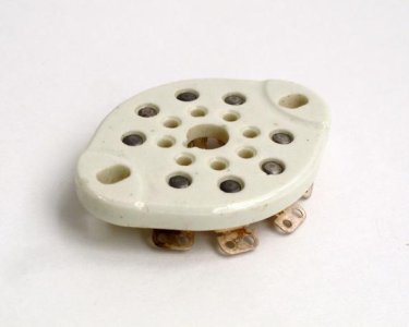
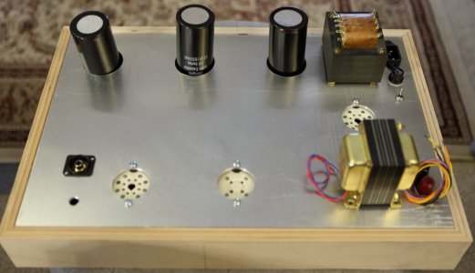
With a few days of unstructured time finally on the horizon, I'll be starting to prototype my build on a 1/8" aluminum sheet. The tube sockets that I have are NOS Johnson ceramic sockets that mount from the underside of the top plate.
Since I imagine it's tough to make a hole larger after discovering that I didn't include enough clearance, how much additional space should I include for clearance around the tube base? If the base of my 300B tube is an actual 35mm in diameter, is a 38mm hole sufficient, or should I go with a 40mm hole? The smaller hole will look neater though the larger hole will potentially provide more cooling. If I go with the smaller hole, is it necessary to make a perimeter of smaller holes around the tube hole for cooling?
Since I imagine it's tough to make a hole larger after discovering that I didn't include enough clearance, how much additional space should I include for clearance around the tube base? If the base of my 300B tube is an actual 35mm in diameter, is a 38mm hole sufficient, or should I go with a 40mm hole? The smaller hole will look neater though the larger hole will potentially provide more cooling. If I go with the smaller hole, is it necessary to make a perimeter of smaller holes around the tube hole for cooling?
Attachments
D
Deke609
Guest
Eric - I don't have an answer to your question, but I just had to comment on the beauty of your metal work! Those look like very precise and clean holes. Are you sending it out, or doing it yourself? If doing it yourself, can you describe your method?
cheers and thanks, Derek
cheers and thanks, Derek
I'd recommend looking through a few tube datasheets to see what the base diameter is listed as. You may find a little variation, but I would imagine 3mm is good enough.
With your mounting plans (which are good), you'll want a rubber washer in the stack so you can tighten down the socket without cracking it.
With your mounting plans (which are good), you'll want a rubber washer in the stack so you can tighten down the socket without cracking it.
EricS
Member
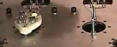
Derek: Sorry that I didn't specify, the mounting scheme shown in the image is not my work nor is it my amp. It's a screen grab from a video that I found of someone showing the "proper" way to mount the Johnson ceramic sockets. The technique is to use a nut as a spacer so there is airflow around the tube socket and up through the tube mounting hole. I'll be making all of my holes on my drill press, not sure how precise I'll be able to make things...
PB: Thank you for the suggestion of using rubber washers! I likely would not have thought of this on my own until I heard something crack while tightening the screws. Maybe I'll use a short stack of rubber washers between the socket and the plate and another rubber washer on the other side of the socket to provide a little "give" so the socket is not rigidly coupled to the top plate.
Yea or nea on a perimeter of air holes around the socket?
The amount of heat generated by the pentode driver and all the parts around it is pretty minimal, so I wouldn't go too nuts with ventilation. The 300B cathode bias resistor and that Japanese style PSU dropping resistor are going to produce most of the heat under the chassis.
EricS
Member
Thanks for the input, as always, PB!
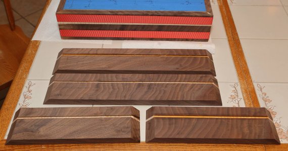
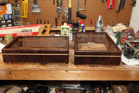
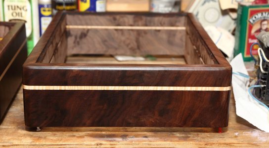
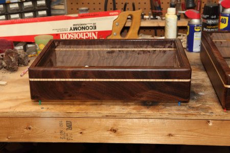
I had great plans of constructing one of my amps this week, but it looks like things like repairing the washing machine (needed a new clutch), repairing the clothes dryer (needed a new motor), and an impromptu several day, 1,400 mile round trip drive to South Carolina in a few days (to start selling my mother's house), my time has been more limited than I thought it would be. Nevertheless, I've been able to actually build 2 wooden bases. They are pretty large, each one measuring approx 18.5" by 12.5". I might need to build a new audio rack as well...
It was a bit of a trick to cut the 45 degree angles as the longer pieces of wood were too long to use the stop on my saw so I could cut them all exactly the same. Instead, I had to hand measure, mark, position, and cut each one by eye. The strap clamps worked VERY well to close up the corners nice and tight - I picked them up on sale at my local hardware store. The four corners were hit with a 1/2" roundover bit and the top edges received a 1/4" roundover. They were sanded with a 220 grit with my new orbital sander (what a wonderful toy!) and I applied some 100% Tung Oil to darken the wood. I'll let this soak in for a few days and then I'll apply some low gloss Formby's Tung Oil Finish (which I'm pretty sure doesn't actually contain any Tung Oil at all). I'll probably end up with 5-7 coats of Formby's before they are done.
I also made one more base out of rough plywood to use as a "construction base" so I don't mess up the nice ones while I'm working on the circuit.
Attachments
D
Deke609
Guest
Those look great already! Nice work.
cheers, Derek
cheers, Derek
Re washers and dryers - we bought our washer and dryer when we moved into our house in 1987. A few years ago the agitator in the washer stopped working and the spin cycle switch under the lid stopped working. I started to look into getting a new washer and I was shocked to see so many reports of recent production washing machines with failed computers, leaky seals and trashed shocks. A little more digging turned up a few recommendations by old time repairmen to stick with older washers as they are much more reliable and actually do a better job of cleaning. So I spent a few bucks replacing a few worn parts and the rather ugly old washer and dryer are still going strong in 2019. I think one could say vintage laundry appliances are more like vintage audio gear in terms of reliability and functionality than, say, vintage motorcycles are (NOT).
EricS
Member
Doc - this is exactly what I've been reading about clothes washers and dryers. The newer ones are all computer controlled and the computer consoles seem to be updated every two years or so. Once a new model comes out, the controls for the previous model seem to be unobtanium, so everyone recommends keeping the old ones running for as long as possible. Just feels that I've been spending all of my time fixing the old stuff lately...
EricS
Member
I had some time during the holidays to get just a little bit of work done. I was hoping to have second round prototype fully built and operational by now, but I'll take what I can get.
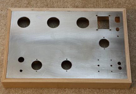
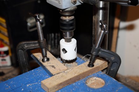
I taped up the aluminum sheet and carefully drew out the position of all of the holes. For the lager holes, clamping the metal to my drill press kept things from moving around while I was drilling. If you "nibble" slowly enough, the hole saw doesn't require too much oil in order to make nice holes. This is the "construction" base that I made from Baltic Birch ply that I had laying around. This way, I won't mess up the nice walnut base with constant movement during construction.
I taped up the aluminum sheet and carefully drew out the position of all of the holes. For the lager holes, clamping the metal to my drill press kept things from moving around while I was drilling. If you "nibble" slowly enough, the hole saw doesn't require too much oil in order to make nice holes. This is the "construction" base that I made from Baltic Birch ply that I had laying around. This way, I won't mess up the nice walnut base with constant movement during construction.
Attachments
Cool!
EricS
Member
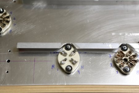
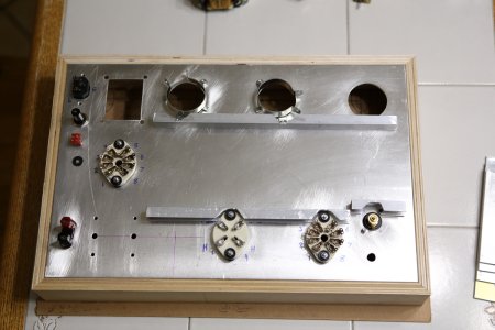
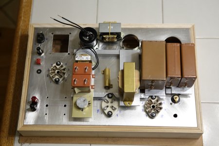
And here is the underside construction. The goal is to keep the screw heads on the top deck to a minimum.
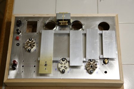
I picked up some aluminum U-channel and 2"x1/8" bar for support of "below deck" parts. It took WAAAAY more time than I thought to do cutting and test fitting, but it looks like things will work out the way I had hope it would. The tube sockets are mounted with neoprene washers all around to protect the ceramic and I think I'll pick up some nylon insert lock nuts to keep things from loosening up after construction.
The U-channel is attached to the socket and cap mounting screws. Then the 2" aluminum sheet will be mounted to the U-channel to hold the remaining parts. It looks a bit more clean underneath than I expected it would given the added hardware.
My original plan was to attach the large wirewound resistors directly to the top plate for maximum heat dissipation, but now I'm wondering if I can insert one more 2" strip and put them there instead, then use some thermal paste between the aluminum parts to spread the heat. Not sure how toasty this would make things or not...
Question 1: How much clearance should I leave in my holes if I plan to powder coat the top plate? I presume the thickness of the powder coat will need to be accounted for- but maybe not. Is using "the next size up" drill bit sufficient for clearance? My hole for the IEC power entry "just fits" and holds the jack in place without screws - I'm presuming I should file it open a bit more...
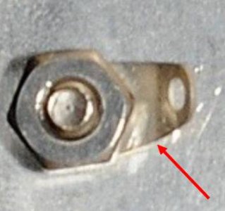
Question 2: Does anyone have a part number for this type of a solder tab? When I search on "solder tab", I keep finding the ones that are meant for soldering rechargeable batteries, not ones with mounting holes in the middle.
I picked up some aluminum U-channel and 2"x1/8" bar for support of "below deck" parts. It took WAAAAY more time than I thought to do cutting and test fitting, but it looks like things will work out the way I had hope it would. The tube sockets are mounted with neoprene washers all around to protect the ceramic and I think I'll pick up some nylon insert lock nuts to keep things from loosening up after construction.
The U-channel is attached to the socket and cap mounting screws. Then the 2" aluminum sheet will be mounted to the U-channel to hold the remaining parts. It looks a bit more clean underneath than I expected it would given the added hardware.
My original plan was to attach the large wirewound resistors directly to the top plate for maximum heat dissipation, but now I'm wondering if I can insert one more 2" strip and put them there instead, then use some thermal paste between the aluminum parts to spread the heat. Not sure how toasty this would make things or not...
Question 1: How much clearance should I leave in my holes if I plan to powder coat the top plate? I presume the thickness of the powder coat will need to be accounted for- but maybe not. Is using "the next size up" drill bit sufficient for clearance? My hole for the IEC power entry "just fits" and holds the jack in place without screws - I'm presuming I should file it open a bit more...
Question 2: Does anyone have a part number for this type of a solder tab? When I search on "solder tab", I keep finding the ones that are meant for soldering rechargeable batteries, not ones with mounting holes in the middle.
Attachments
D
Deke609
Guest
Question 2: Does anyone have a part number for this type of a solder tab? When I search on "solder tab", I keep finding the ones that are meant for soldering rechargeable batteries, not ones with mounting holes in the middle.
They are stupidly difficult to search for. Here's a DigiKey link (note: you need to search under "interconnects"!? - who would think to do that?): http://www.digikey.com/products/en/connectors-interconnects/terminals-solder-lug-connectors/401?k=connectors
Even if you buy a hundred, they are still ridiculously expensive for stamped sheet. There must be a cheaper source.
cheers, Derek
The solder lugs are indeed ridiculously expensive but they are brass, so perhaps that helps to account for some of the cost.
You'll have to post the resistors you're using and the heat each dissipates to really know how much of an issue you may be looking at.
For the powder coating question, I keep a chainsaw sharpening file close at hand, and I can pop that into any holes that get too small from the powder and just file it out. You can also run a thread tap through them.
EricS
Member
PB: Both resistors are rated at 50w dissipation: https://www.mouser.com/ProductDetail/Vishay-Dale/RH05050K00FE02?qs=sGAEpiMZZMtbXrIkmrvidDNaDpN5VXc5qswg6VdgV68%3D
The 50k PSU bleeder resistor will dissipate 425*425/50,000 = 4w of power all of the time.
The 1k cathode bias resistor will dissipate 70*70/1,000 = 5w of power all of the time.
Both on the same sheet will produce 9w of power. My mounting options are to attach them directly to the 11x17 base plate (most optimal cooling) or to put them on another strip of aluminum mounted between the B+ choke and 300B tube socket. This strip will be attached to the U-channel, which is then attached to the base plate. If I put thermal paste between everything, it might work out?
I think I'll need to make some temp readings once everything is wired up and running.
As for powder coating, I presume it won't chip/flake off of the top surface if I need to take a file to the edge of the hole - is this true?
The free air rating of the 50W resistors is 20W (it's in the datasheet), and I'd derate that a little more, but you're still plenty safe. The heatsink area to get 50W of dissipation out of those is 1 square foot of 0.060" AL per resistor, so you won't be anywhere close to that with two resistors.
The heatsink paste is unlikely to be necessary.
The heatsink paste is unlikely to be necessary.
Similar threads
- Replies
- 2
- Views
- 307
- Replies
- 45
- Views
- 1K