CCS Loaded Parafeed Output - Design Considerations?

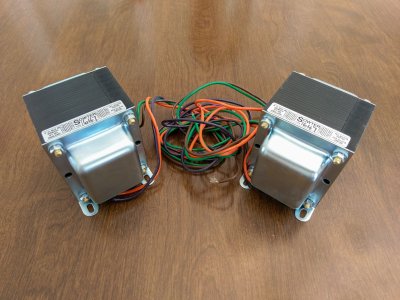
Hey PB (and PJ if you happen to stop by  :)) ) - still working on my 801A A2 amplifier, still waiting for the Sowter OPT, they are a bit hampered with COVID so I think building is slow, should have them soon.

Wanted to show you something pretty cool and also ask if you have any input on something else.  I have been hanging around diyAudio and discussing ideas for these high-gain CCS fed pentodes.  A certain someone who maintains a certain DIY tube blog suggested a fancier g2 supply for my pentode driver rather than the 1Meg resistor from B+ I was using before.  The idea is to use a local feedback mechanism with the DC voltage fed to g2 via FET, with the voltage derived from a divider from the mu output of the CCS.  Seems similar ideas are floating around a few places, but the one that inspired the suggestion to me was done by JC Morrison on his transconductance gain block here:

http://www.labjc.com/?p=5317

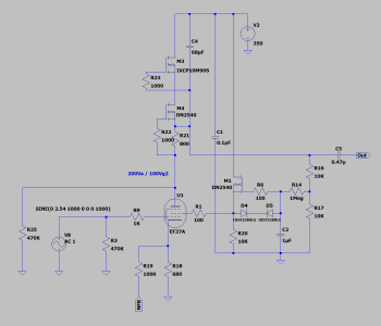
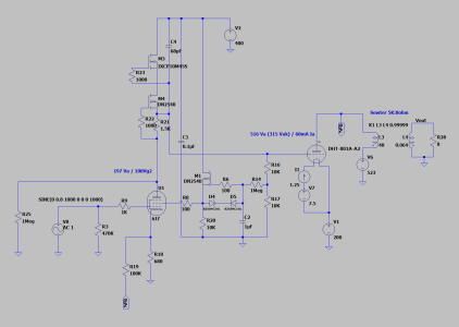
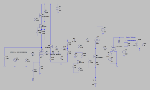
In this arrangement, any drift in the plate voltage is communicated down to the screen, I put together some Spice models, built out the circuit on a protoboard and gave it a shot, schematic below.

What I found is this setup provides VERY stable anode / screen voltages.  At maximum output into a 8ohm dummy load, sine waves as well as real music, I never see a voltage drift more than 0.5V on either, pretty nice, so this is going in the final design.  With the exact setup I have shown below, I am getting 0.14% THD at 1W out of the amplifier.

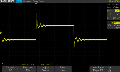
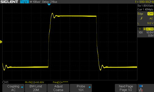
This design is 95% of the way there, just a matter of dialing in the feedback / output impedance / FR / harmonic profile when the Sowter stuff gets here.  The only niggling thing left is some somewhat ugly overshoot / ringing I am seeing on square waves, shown below as well, the output from the EF37A.  The amplifier is stable, perhaps it is a non-issue or will resolve with the Sowter OPT, still need to do some more troubleshooting, but the Lundahls seem quite prone to this type of ringing, we will see.


Stay safe fellas!  Hopefully 2021 is a better year.
 

Attachments

  • 801A A2 Screen Feedback.png
    801A A2 Screen Feedback.png
    32.1 KB · Views: 17
  • SDS00001.png
    SDS00001.png
    18.3 KB · Views: 6
I changed C2 to 4.3uF without any change in the overshoot / ringing.  I discovered the ringing goes away with the feedback loop disconnected.  The outputs of the EF37A and source follower are clean, it originates at the output stage.  The ringing is 45-50kHz when open loop, roughly 20kHz closed loop.  Adding any feedback compensation capacitance starts to roll off the HF, so that isn't a viable solution, especially with it being so close to the audio band.

I wonder if this is just another issue with the LL9202 OPT and it will go away with the Sowter iron in place, maybe I should just wait it out and see.

Below is the 1kHz square of the 801A plate with the feedback loop disconnected.
 

Attachments

  • SDS00013.png
    SDS00013.png
    14.8 KB · Views: 7
Agreed, these Lundahl OPT are so quirky, I think it's best to just wait it out.  Not sure what I will do with them afterward, despite their oddities they are very nice sounding transformers.  Thanks again, PB.
 
What do you think of this PB...

A friend of mine made a comment that got the gears turning on how to simplify my 801A A2 design.

Originally, I was using a source follower buffer to drive the 801A grid into A2 with V+/V- supplies such that it could swing from +60 to -70V. What I am experimenting with (in LTSpice) is eliminating the source follower, elevating the 801A filaments (~200V), and direct-coupling the 801A grid to the mu-output of the EF37A CCS. This does away with the V+/V- supplies, allowing the grid to swing positive/negative with respect to the filament, and eliminates a coupling capacitor. The output impedance of the DN2540 appears low enough to provide the grid current for A2 and does not seem to be adversely affecting the plate current of the EF37A. Could be different in the real world, I've attached my functional but not refined schematic below, 6J7 has been substituted for the EF37A for proof-of-concept purposes. Thanks for looking.
 

Attachments

  • 801A DC Coupled.png
    801A DC Coupled.png
    43.1 KB · Views: 23
I would rather see that 200V be a negative rail sitting under the driver so it doesn't have to deal with the craziness of the output stage.
 
Hey PB - didn't see your reply for some reason.

Yeah, the more I have looked into this, I think that while it helps with some issues, it creates a host of other ones.  For instance, the bias of the output tube would be highly dependent on variances between different input tubes, changing each EF37A driver would require a manual adjustment.  Also, as the EF37A comes up to bias, the plate voltages initially swings up to 250-270V or so before settling down to 200V, meaning the 801A grid will momentarily be at +70V, which will likely blow my plate fuse.  Even if I increase the rating of the fuse, seems to me putting that stress on the 801A with each startup is not good design.  It also increases my B+ requirements, pushing up against the limit of 600V components...

I may just go back to the old setup!  Why didn't you tell me the 801A is such a pain, PB?!  (Just kidding, of course).

In your 801A A2 amplifier, what kind of harmonic spectrum were you seeing?  So far, with the NFB what I have measured as been a higher H3 than H2, not your typical SET dominant H2 spectrum.
 
Hey PB - Sowter iron arriving in the next few days.  I've abandoned my idea above on elevating the 801A filaments, back to using a negative bias supply.  Quick question for you - on your 801A A2 build, did you use a dedicated transformer for your negative bias supply, or did you run it off the 801A B+ secondary?  Right now, I am using Pete Millett's shunt-regulated 300B bias supply for my source follower V- (adapted for my use).  It's a bit unwieldy though since it has a dedicated toroid, trying to slim things down a bit.
 
Darn!  That would be perfect...perhaps I'll look around, see if I can find something suitable.  Thanks for the $0.02.
 
Actually, quick follow up question for you PB if you don't mind: say I found a suitable mains transformer with an appropriate B+ winding for the 801A and a ~100V winding for the source follower V-.  In that case, it would be appealing to run the source follower V+ off the 801A B+ winding.  The concern here is the stress that could potentially be placed on the 801A grids if driven excessively into clipping in A2, as the V+ would supply any voltage asked of the driver.

Do you think that is a good reason to limit the source follower V+ supply, such that it does not run the risk of excessively high positive grid voltages? My initial though was to limit the peak-to-peak voltage swing of the pentode driver by simply applying the appropriate amount of feedback such that the remaining gain is ONLY enough to just clip the 801A.

Just to summarize, do you think I could use a 300V supply on the source follower drain and not worry about stressing the 801A grids by limiting the gain of the drive via feedback, versus using a lower voltage V+ supply to protect the grids, but making the power supply larger and more complicated since I would need another lower voltage transformer for the V+ supply...

Hope that makes sense, as always, I appreciate your time :)
 
You could certainly use an avalanching device to add some protection there, though I've never been able to flog one of these amps hard enough to run into that issue.

 
I hear ya, thanks, I'll think it over some more.  I doubt it would ever be an issue in real life use, just one of those hypothetical type of things.  Maybe I don't use the maximum amount of NFB and I have some extra gain on the driver and my cat paws the volume knob and melts my 801A grids LOL who knows.
 
Got the Sowter iron, 5K:8ohm 60mA.  Designed the PCBs for the EF37A g2 supply, source follower, and my 0V 801A bias supply.  I don't know if I mentioned it, but what I am trying to do is use a 6.3VDC regulator on the EF37A heaters, then drop that across an adjustable voltage divider to make the gate of the source follower FET a few volts positive, such that I get a perfect 0V bias point.  We'll see how it goes, need to round up all of these parts, wait for a warm spell, then throw together a single channel and measure.


Attachments

  • IMAG2803.jpg
    IMAG2803.jpg
    1.2 MB · Views: 13
Yeah it is one of the final challengers I am facing, that and the driver g2 supply.  Should be able to adjust from around +1.5V to -3.5V on the grid, we’ll see how stiff the regulator is, hopefully I get it right the first time around.
 
Hope you and everyone at Bottlehead had a nice holiday, PB.

Wanted to show you what I came up with as a solution for the 0V bias point problem, I think this is a good approach.  I got rid of the source follower FET!  Switched to a cathode follower, a 6BX7 with the plate current set by a current sink.  The negative grid voltage is generated by a LND150 CCS and a 56K resistor to ground.  Since the CCS is adjustable, the cathode voltage can be adjusted to either side of 0V by setting the grid voltage appropriately.

I think a single section of a 6BX7 will get the job done, but could always use two and parallel both triodes if necessary.


Attachments

  • 801A 6BX7.png
    801A 6BX7.png
    50.2 KB · Views: 11
Back
Top