CCS Loaded Parafeed Output - Design Considerations?

Thanks, I'll give the OPT changeout some thought, I have an order pending with Sowter right now actually...it might not mean much considering I am only three scratch builds into this thing, but this might be the best amplifier I have ever heard...no kidding, it's that good.  So perhaps it is worth squeezing out some more performance with a wider bandwidth OPT, assuming the LL9202 are not a large part of why it sounds so great.  I'll sleep on it!  For a week.

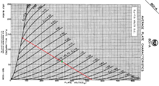
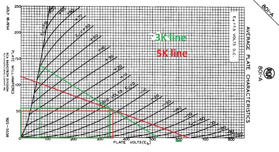
I think the most I have ever heard of someone getting out of an A2 801A is 8W, you didn't mean to imply you could get 10W out, did you PB?
 
Wow that would be interesting.  I am in the process of reworking my 6A5G amplifier, transplanting into a new chassis.  It uses 3.3K 60mA OPT, maybe I will throw them in this prototype and see how it works out.  Only thing is I would have to rethink the bias supply, it uses a LND150 CCS and a 56K resistor to ground to set the bias.  If I just used a resistor to ground instead, the bias would be set by the gate-to-source voltage of the FET buffer, something like -4 to -5V.  Wouldn't be adjustable though, have to look into it more deeply and think it through...
 
Just be sure your loadline still makes sense in terms of giving you the power you are expecting.  I ran the 801A at 300V/60mA (the 60mA was measured as plate+grid current) and got about 8.5W. 
 
For sure, would have to alter the B+, bias supply, etc. to give this a try, but shouldn't be too bad I don't think.

I have to admit PB, I am not seeing how you got 8.5W out of the amp with a 300Va / 60mA bias point and a 3K load, I believe it, but something is missing.  I've attached a load line, I am seeing at max something like 360Vpp into 3K, limited at the positive peaks, that's about 5.5W by my math.  What am I missing here?


Attachments

  • 300v 3K LL.png
    300v 3K LL.png
    164.5 KB · Views: 10
Hmmm still don't see 8W at that load line, but maybe it is the real world difference between the datasheet and live implementation?  You aren't the only person I have heard that from, I know of another builder who used a nearly identical bias point, 300V 60mA, and got 8W output.  Maybe there is some magic in that bias point.
 
Fair point, well over the next week or so, going to see if I can throw these 3.3K 60mA OPT in the prototype and see what kind of sound / power output we get!
 
PB - I tried out my 3.3K transformers this morning.

I nixed my bias supply and just used 520K to ground, not ideal since the grid voltage isn't really adjustable, it is fixed by the gate-to-source voltage of my FET buffer, so -3.1V on the grid.

I was able to adjust my bias point to some degree using the trimpot on the Maida regulator I am using.  I dialed it in to a 335Va / 57mA / -3.1Vg bias point.

With this, I am getting 156V to 524V peak-to-peak swing, with the 801A hard clipping beyond 524V on the positive peaks.  This results in 16Vpp into 8ohms, about 4W out.  This is pretty darn consistent with the datasheet if I draw out the load line.

Ideally, I would get to a true 0V bias point and 320V with a 3K (rather than 3.3K) primary impedance, it is doable, have to put +3V on the gate of my FET.  At that bias, if the datasheet is to be believed - and so far has been consistent with my measurements - even assuming no copper losses, that makes 5.5W into a 3K load.  Even if you did something crazy and biased at +10V on the grid at 280V on the plate, that is 400Vpp into 3K, makes a 6.4W.

So, I am just not seeing how it is physically possible to get 8W out of an 801A A2 amp at any 0V bias point.  Am I missing something here?

I added additional NFB given the reduced gain needed from the driver stage, got the output impedance down to 2ohms.  FR of the LL1620 below, think I am hitting transformer limitations on the high end again.

Thanks for your thoughts.
 

Attachments

  • 801A 3.3K 335V 57mA.png
    801A 3.3K 335V 57mA.png
    807.5 KB · Views: 6
  • FR 3.3K Optimized.png
    FR 3.3K Optimized.png
    27.2 KB · Views: 6
Here is my set of load lines, as I had considered 3K and 5K iron for this project.  This is swinging 520 to 70V, so 161V RMS. A 3K:8 is about a 19.5:1 step-down, so that gets you 8.25V at the speaker posts, which is just over 8.5W. 


Attachments

  • 3K loadline.jpg
    3K loadline.jpg
    683.4 KB · Views: 22
I see, thanks for the pic.

But the amp is going to hard clip asymmetrically on the positive peaks, is that not typically considered when quoting an amplifier's power output?  This is exactly what I see in my measurements, the positive signal is chopped off above 524V whereas the amp can continue to swing downward until the plate hits saturation at 70V or so.
 
The 8.5W was at 10% THD I believe.  You'd have to make a plot of THD vs. power to determine where you'd say hard clipping starts.  The asymmetrical clipping will be pretty brief IMO in the grand scheme of things.
 
Gotcha PB, I see now where I was making the mental disconnect.  Well regardless, this is basically a full A2 amp in this setup, going to give it some listening time, then decide how it compares to the LL9202 setup with the 6.5K primary.  Thanks for letting me pick your brain, yet again.
 
I made an error in a previous measurement PB, my 0.38ohm output impedance wasn't reproducible, so something was off.  I was more consistently getting 2.8ohms output impedance with a 220K plate resistor on the EF37A.  I wanted to improve this, but using a bypass cap on the cathode of the EF37A degraded the sound quite significantly.  I decided to try the CCS setup.

I simulated in LTSpice to get ballpark values, then went for it.  I used 1.56mA out of a cascode CCS with a 470K resistor to ground. I figured maybe if I used a larger value without going crazy, I might not have DC bias instability issues but could still get a damping factor of 3 out of the amp.  EF37A bias point was Va 240 / Vg2 95V / Vk 2.77V.  Leaving the cathode degenerated, I was still able to get a open loop mu of 125 out of the EF37A.  I returned to my 6.5K LL9202, I think the sound is better than the full A2 setup with the 3.3K LL1620.

THD @ 1W 0.44%
Output Z 2.44ohm
-1.67dB @ 20kHz

Bandwidth improved as well.  I monitored the plate and cathode voltages of the EF37A with music playing at varying volumes, did several shut-downs and start-ups as well - the bias does not drift, it finds its way right back to the same point every time.

I think I'm gonna stick with this approach and improve up on it!

FR and unclipped full output below, this is a 5W amplifier :)


Attachments

  • FR CCS Optimized.png
    FR CCS Optimized.png
    27.2 KB · Views: 4
  • SDS00006.png
    SDS00006.png
    19.8 KB · Views: 4
Still working on this tricky amplifier, I was finding that adding capacitance to stabilize the feedback loop was hurting the HF response and there is none left to spare.  I pulled the trigger on a pair of 5K:8 60mA custom OPT from Sowter UK, no more of this bandwidth issues from the Lundahl LL9202, I'll have to repurpose them.  Specc'd the transformers for 60mA in case I want to go for a 0Vg bias point, something like 330V 55mA, either than or 360V 50mA.
 
I kind of feel like I'm corrupting you...

I've had Sowter make plenty of iron for me over the last couple of years.  Spending the dough on their stuff lets you focus a lot more on the circuit itself rather than worrying about what the iron is doing. 
 
No worries on the corruption :) I have an order pending with Sowter for another project, in truth I was already considering the switch after all the frustration with the Lundahl transformers.  I am very committed to this build, so I think it will be worth it, could always resell the Lundahls.  Good thing to be able to focus on the circuit, having some issues with ringing on square waves that I am working through.  Maybe the issue will disappear with the Sowter OPT in place, wouldn't that be nice.
 
You could also experiment with a zobel across the secondary.  Heck, you're paying Sowter for a custom wind, Brian might be able to tell you the optimal values for R and C.
 
Good idea, I'm wondering if it is an artifact of the Lundahls specifically.  I checked square waves on the pentode and source follower with the 801A out of the circuit (no feedback), no ringing whatsoever.  It is present on the primary and secondary, near the audio band based on the period of the ringing, roughly 50uS, so around 20kHz, don't want to shunt 20kHz to ground. 

Anyway, I'm probably going to shelve this beast until the Sowter OPT get here, probably not worth troubleshooting issues that might go away with a more optimal iron.


Attachments

  • slQobdX.png
    slQobdX.png
    15.4 KB · Views: 7
Back
Top