CCS Loaded Parafeed Output - Design Considerations?

If you bypass the bias resistor, you can turn it into a pot in your build and just adjust it to get the plate voltage to sit where you want it to. 

Alternatively, you don't have to use a CCS at all.
 
That's a good idea!  Let me think on it.

Yeah, a 75K-100K resistor on the plate would get the job done.  I would lose the very low output impedance from the mu output of the CCS though, but in terms of HF rolloff, unlikely it would make a big different with the source follower buffer.  I'll probably give both methods a shot and see what measures / sounds better.  The resistor load certainly is less of a bother...
 
Yeah, overkill for sure.  Distortion is significantly better in the sims with the CCS load however, 0.25% THD with CCS at 1W, 0.42% THD with the resistor load at 1W.  I'll give them both a go and see what the real world has to say about it.
 
When you go to the plate curves and try to draw out the DC load line for the pentode driver, you'll see the plate voltage problem pretty clearly.  This is made worse by a fair amount of your bias voltage being relatively fixed because of how the feedback is setup.  By going to more of a resistive plate load, you can stabilize the DC operating point a little bit.  The extra 0.2% THD is probably worth the trade.
 
I see...very small changes in cathode voltage will result in drastic changes in plate voltage and bias point.  Is this what you are referring to, PB?  It does seem a good tradeoff for the sake of simplicity.  As I have continued to try different operating points, balancing the CCS current, plate voltage, cathode voltage, while maintaining the appropriate amount of NFB is...difficult.  They are interdependent, getting the operating point dialed in with the CCS will be quite a hassle.  I had hoped to leave an electrolytic out of the signal path by leaving the cathode unbypassed, I have had good success with this in the past with CCS loaded triodes, but I suppose that may not be an option with a resistively loaded pentode.
 
L0rdGwyn said:
I see...very small changes in cathode voltage will result in drastic changes in plate voltage and bias point.  Is this what you are referring to, PB?  It does seem a good tradeoff for the sake of simplicity. 
Yes, we ran into this issue with our Eros phono kit, which uses a CCS loaded pentode with a resistive load from plate to ground.  PJ cooked up a servo circuit to deal with this issue.


Interesting, I think I will save myself the headache and just go with a resistive load, thanks for the warning.  If I could pick your brain yet again PB, is there a practical method to determine to appropriate phase compensation capacitance in parallel with the feedback resistor?  I have been told by some that the value isn't critical, just throw something ballpark on there and check for oscillations / square wave ringing.  I have read others that will put a scope probe on the input and output and increase the frequency on a signal generator until they find 180 degree phase shift.
 
You may not need one at all!  You could look at 10kHz square waves and add/subtract capacitance to examine the shape of the waveform.
 
Good point, I had wondered if I might not.  Okay, I'll give that a go and keep some capacitors handy just in case.  As a non-engineer guy picking this stuff up, finding good resources on specific topics can be tough, its a big help to be able to bounce things off people, so thanks again.
 
Alright PB, I have some preliminary pentode results...

Just to recap, in the original design with the 841 and no NFB, I used a 420Va / 40mA Ia / -21Vg bias point for the 801A with an 11K:8ohm output.  My FR stated to roll off around 6-7kHz and my -3dB point was 16.5kHz, my output impedance was 4ohms.

For this new NFB pentode setup, I figured I could get the output impedance down to a reasonable level even if I rewired my OPT for 6.5K:8ohm.  I rebiased the 801A to 360Va / 50mA Ia / -10Vg with the 6.5K primary.

The pentode I used is the Mullard EF37A.  I biased it with a 400V B+, 200K plate load, 200V on the plate, 100V on g2, 3.2V on the cathode.  NFB was taken from the plate of the 801A to the cathode of the EF37A (can't say exactly how much, will have to run some sims to get an idea of the open loop gain).  Ended up with a mu of 20ish with the NFB added.

Output Z: 2.8ohm
THD @ 1W: 1.2%
Power output: 4.7W into 8ohms.

Frequency response below, vastly improved from the build with 841 driver and no NFB.  Doesn't truly start to roll off until around 16.5kHz, down 2.5dB at 20kHz.

Going to play with the bias and load of the EF37A to see if I can squeeze out a little more gain.  Wondering if I should try the same with my 11K:8ohm OPT wiring and 420Va / 40mA Ia bias point.  I was expecting more than 4.7W with this new arrangement, will have to give it some thought, must have made a mental error somewhere.
 

Attachments

  • FR 6.5K EF37A 200K Load 50K NFB.png
    FR 6.5K EF37A 200K Load 50K NFB.png
    27.6 KB · Views: 12
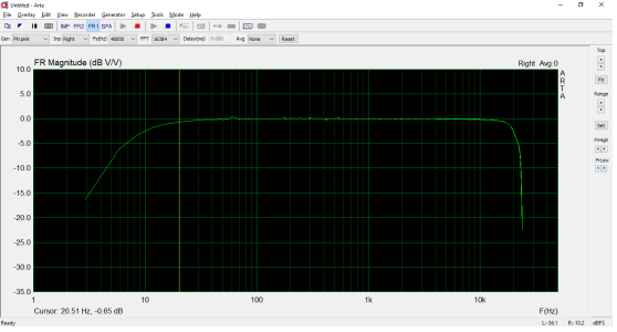
I figured it out PB, with my OPT wired for 6.5K:8ohm, the copper losses go up from 0.5dB to 0.8dB.  I am getting around 572Vpp into a 6.5K load, with the copper losses I should be getting a little over 5W out, and that is what I am seeing.  The 801A is clipping asymmetrically though at the positive peaks with my 360V 50mA bias point, might drop it down to 350V 50mA and see if I can get a more symmetrical clipping, my OPT are made for 50mA on the primary, so can't crank up the current, that would put me at 17.5W plate dissipation, so not a bad place to be for longevity.

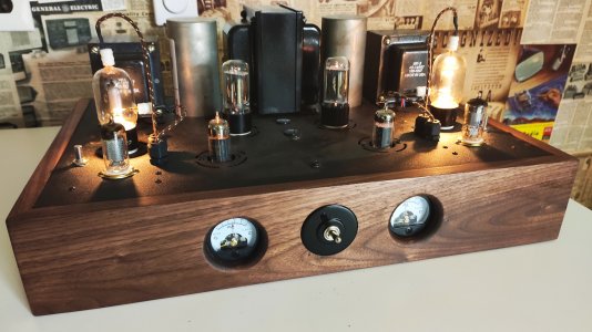
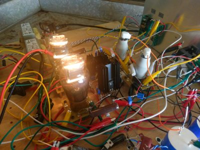
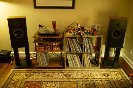
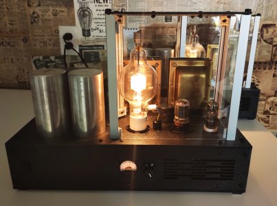
Thanks for suggesting the pentode NFB route PB, someone else had suggested it too early on in my project, I poo poo'd it at the time, "NFB in my amp?  Never!"  I won't be saying that ever again.  I lugged this monstrosity into my house today (it is built on a piece of plywood, picture below).  Gave it a listen with my Snell J/II that I recently restored.  This amp sounds INCREDIBLE, I mean, really it is something else, even compared to my 45 parafeed amp and my 6A5G SET, which are no slouches IMO.  The detail, bass definition, eerie level of imaging...

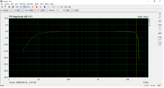
I was listening with headphones today with a 8.2ohm resistor paralled on the output, at a pretty high listening volume for headphones.  I left the volume where it was, unplugged my headphones and measured an FFT.  The distortion was 0.023%.  So super low THD with headphone listening, around 1.2% THD at 1W into 8ohms.

Going to further optimize the NFB tomorrow and maximize it while still driving the 801A to clipping.  These EF37A tubes are pretty cool.
 

Attachments

  • IMAG2428-2.jpg
    IMAG2428-2.jpg
    1.1 MB · Views: 18
  • DSCF5808.jpg
    DSCF5808.jpg
    1.2 MB · Views: 14
Nice!  You are not the only person I know looking for the perfect amp to go with 8" Snell 2 ways.  These are my current A2 amps that get the most use.  The feedback loop I use is from the output tube plate to the plate of the driver pentode. 
 

Attachments

  • IMG_20200426_221810.jpg
    IMG_20200426_221810.jpg
    2.6 MB · Views: 19
WOW!  That is something, what tube is that and how much power?  Cathode follower is a 6BL7 or 6BX7?

I made some changes to the EF37A plate load this morning and optimized the bias point / NFB.  I used two 1K trimmers stacked on the cathode and bisected by the feedback resistor so I could adjust the bias point and feedback loop.  I maximized the NFB while keeping the 801A just below clipping at max signal input (2Vrms) and kept the EF37A at a 220Va / 96Vg2 bias point.

Now getting an output impedance of 0.38ohms!  And the FR has improved further, I wonder if I am hitting transformer limitations at this point given how low the output impedance is.


Attachments

  • FR.png
    FR.png
    27.2 KB · Views: 5
Yeah, you're running up against transformer issues there.  The good news is that there are tons of 5K transformer options that aren't so limited. 

The amps in the photo are 100TH with a 6BL7 as a directly coupled cathode follower to drive the grid of the 100TH.  The extra half of the 6BL7 regulates the B+ for the cathode follower, which is something PJ suggested when he was visiting last year.  The input tube is an EL41, which was about the only pentode I could find that didn't care too much about high plate voltage and had the middle of the road transconductance that made it work properly in the circuit. 
 
Funny to think I am running up against transformer issues, these are from a reputable builder, although I suspect the designer may have sacrificed some HF extension for a high primary inductance, 100H on a 6.5K primary, these can be rewired for 11K and 23K as well, I thought I would be using them at 11K.  The thought of replacing them isn't super appealing, will have to do some soul searching and decide if 17kHz is good enough, certainly beyond my hearing ability.  I'll think about it, but the sound I am getting right now is sensational, the bass is jaw dropping...worried if I replace them I could end up with something less satisfying, "the devil you know is better than the devil you don't."

The 100TH...that one is out there, never even heard of it!  Very cool looking tube though.  I imagine when you have been building tube amps as long as you have PB, you have to get more and more esoteric to stay occupied.  I also imagine they keep you nice and warm in the cold winter months :)
 
When you make a transformer that is either 6K or 12K, depending on how you wire/load it, that is already a bit of a compromise.  I think this is more doable with a 5K/2.5K, as it's easier to land right in the middle and make a fully optimized 3.75K:6 transformer and ratio it accordingly.  It's still a compromise though!

You are using the big Lundahls right?  I have been pleasantly surprised by the performance of the 5K One-Electron output transformers, especially up top.  They aren't insanely expensive and are plenty big to get all the power out of an 801 that you could possibly get.  The datasheet says you'd be -1dB at 30kHz with this iron, but the last amp I made with them was -1dB at 42kHz, which was rather surprising.  Said amp was -1dB at 22Hz, so about the same down low as your current transformers.
 

Attachments

  • IMG_20200526_215057.jpg
    IMG_20200526_215057.jpg
    2.8 MB · Views: 20
Interesting, always compromises in this hobby.  Well thank you for the recommendation, I'll check out those One Electron transformers, -1dB at 42kHz, that's pretty impressive.  That's right, I am using the Lundahls, these are the LL9202.  I've used Sowter as well, tried reaching out to Magnequest recently for a potential project I am cooking up but never heard back.  I've liked the sound of the Lundahls so I have stuck with them, but always open to trying something else.  Thought about trying Electraprint as well, they seem to have a good reputation in the DIY world.
 
If budget allows, Sowter and Monolith are really solid options.  For a ~10W amp, the prices aren't completely insane either.
 
Back
Top