Need Help with First Tube Build - WE91 300B Parafeed Derivative

Got it, my thanks to both of you.  My primary concern was that the heater circuit also carries the B+ supply from the rectifier to the PSU caps, so it will have ~450vDC across it until the caps ramp up to steady state.  I didn't want to put a resistor there that was not rated for that voltage difference...
 
EricS said:
My primary concern was that the heater circuit also carries the B+ supply from the rectifier to the PSU caps, so it will have ~450vDC across it until the caps ramp up to steady state. 
The heater circuit is floating and it has 5V AC across it.  It is completely unaware of the DC voltage in question.  It is true that the DC current needed to charge those caps will have to pass through these resistors, but that current is limited by the power transformer, the 5AR4, the size of the caps/chokes, etc.  When you turn the amp on, there will be 0V DC at the first filter cap and the 5AR4 will have zero emission (no current flowing) to charge up that cap.  The voltage seen by the filament dropping resistors at this time will just be 2A*0.05V=0.1V.  You may see a bit more than that since the 5AR4 filament is cold and will draw a bit more current until it's hot.  Without the filament being hot, the high voltage AC humming along on the rectifier plates is not in the equation.

A quick simulation in PSUD (which does not model the slow warmup of a tube diode) shows the current required to charge the power supply peaks briefly at about 2.25A, then settles down to 164mA almost immediately.  I worked on bigger amps with 1A fuses between the rectifier and the first filter cap as an extra safety measure, which is another indicator of how gnarly the charging current is when a tube rectifier is used. 
 
Ah - now all of the pieces are coming together for me!  There will be a current and voltage peak across the 0R05 resistor when the empty caps are first charged, but because of the low resistance of the resistor and the "slow" voltage ramp up of DC voltage out of the 5AR4, there will never be a 450v delta across the resistor...  This was my mistaken assumption.

I can't quite get the PSUD simulation to duplicate the exact voltages that I've measured in the amp (I'm unsure about resistance in the B+ winding in the transformer and I've estimated the reactance of the caps at 60R for 120Hz), but it seems close enough that I have a better picture of what is going on now.  The peak current on the 0R05 resistor is the same as the peak current going into the first cap of about 2.4A.  The voltage across this resistor closely follows the pattern of the current draw, which settles down to a very small amount once the PSU achieves steady state.  I'm seeing a peak voltage across this 0R05 filament resistor of less than 0.15vDC before it settles down to somewhere in the 0.02v range for steady state.  Even if I'm off by a few orders of magnitude (which I'm pretty sure I'm not), things still look good to me.

Many thanks, Paul and Paul!  I keep thinking I should go take an intro EE course from my colleagues across campus...  I've got many of the concepts in my head but sometimes I don't quite see how they all interact with one another.

Next up is re-reading Morgan Jone's chapters on transformer mounting to the chassis plate and looking over some of the great builds I've seen documented here so I can order all of the mounting hardware, grommets, shoulder washers, etc that I'll need next.
 

Attachments

  • 300B B+ R1 voltage simulation.jpg
    300B B+ R1 voltage simulation.jpg
    237.2 KB · Views: 13
  • 300B B+ R1 current simulation.jpg
    300B B+ R1 current simulation.jpg
    186.3 KB · Views: 10
That's pretty cool. A couple of milliseconds of 2+ amps @ 120 mV - so approx. 1/4W.  And the quoted specs for your resistors indicate that they can withstand up to 15W of dissipation for 5 seconds and a constant 3W dissipation.  You're golden!
 
Yeah, that was totally non-intuitive for me: any old 1/4w resistor will work for this application!  It's my strong desire for way over-engineering things that pushed me toward a 3w part for this purpose. 

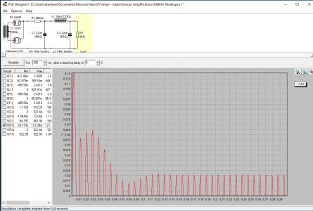
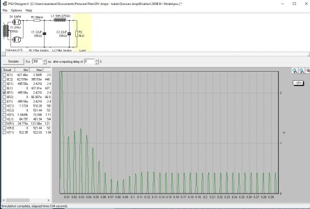
The pair of 0R5 Mills MRA12 wirewound resistors that I put on the 300B filament to tame the voltage get toasty warm at 60c.  1.5A of current pass through those guys, so they dissipate about 1.125w of power each.  Derating for temp, they're still good for 75% of their rated power at 100c, so things should be good here.  The 300B filament PSU is a CLCR (1,000uF, Hammond 155B, 10,000uF, then 0R5) and I keep wondering whether the better solution is to torture the resistors at the end or torture a smaller first cap in order to hit a 5.0-5.1v target.  Using the CLCR approach, ripple on the heater is about 9mV - this wasn't really my goal, but is a nice side effect of clamping down on the voltage.
 
You also have the DCR of the power transformer high voltage winding limiting current, as well as the impedance of the tube rectifier itself.

For the amp I last worked on with the rectifier to B+ fuse, it had blown because the owner had the amp plugged into a power strip and he turned the power strip off with the amp running, then back on a few seconds later.  This was enough time to discharge the caps but not so much time that the tubes actually cooled off much.  Still, this was a 1A fuse fed by 5AR4s (two per amp) into a 100uF filter cap, so I have reasonable confidence that in your particular amp, you're unlikely to even see 1A of peak draw.
 
That's interesting - there is a good deal of value knowing that the simplifications built into PSUD actually present more of a "worst case" scenario that we are likely to find in actual application.  Cool stuff!
 
They can go the other way too.  There isn't really anything in PSUD to track how hot a solid state diode will get.  I've had some actually fall out of a PC board because they got so hot and melted the solder that was holding them in.  The same goes for ripple current rating in capacitors, PSUD will at least give you a number for that, but you have to pay attention to the parts that you're buying or you'll let the stinky goop out. 
 
I just received the aluminum sheets that I'm going to use as the top plates for the amp.  I ordered three that are 11" x 17" - one to prototype and make a mess of, and two for the finished amps.

Now that the amp is verified working properly (no longer using a bad driver tube), I made some additional measurements of bandwidth and gain.  The bandwidth measurements are particularly interesting:

With the 250k grid leak resistor: -3dB bandwidth points are 20Hz to ~17kHz - not really sure that I can hear above 17kHz ;-)
With the "Nickel" BCP-16 Grid Choke: -3dB bandwidth points are 21Hz to 11kHz - wow, what a nosedive!
With the "High Nickel" BCP-16 Grid Choke: -3dB bandwidth points are 23Hz to 11.5kHz - same dramatic dropoff
Not sure if the sound quality from the chokes is better, but based on bandwidth, the 250k resistor will stay for sure!

Clipping behavior is also pretty interesting with the various configurations for grid leak:
With 250k resistor, max input signal is 0.68v AC RMS before onset of clipping: max output is 7.43v AC RMS into an 8-ohm load
With both Nickel and High Nickel Grid Chokes, the max input signal before clipping is 0.47vAC RMS, but I got just a pinch more output at 7.50v AC.
Curious that the chokes deliver (marginally) higher input sensitivity and higher output than the Grid Leak Resistor did...

Overall output level is just shy of 7w into an 8ohm load (~20dB gain).

Overall noise/ripple measurements are very nice!  All of the following measurements were made with the RCA input shorted:
Speaker output: 0.4mV AC noise level
300B plate voltage: 0.0mV AC ripple
300B filament voltage: 0.04mV AC ripple with CLCR configuration
6SJ7 Driver Plate voltage: 0.05mV AC ripple

This amp is VERY quiet!  With my ear on the speaker driver, I can't hear any hum at all!

I also attached an updated voltage chart.  My AC mains tend to run 123 to 125 most of the year.

Time to start making holes in the top plate and assembling the wooden bases...


Attachments

  • Nov 26 Voltages.jpg
    Nov 26 Voltages.jpg
    31.9 KB · Views: 14
If your gear will do a graph of frequency response, that may be useful to look at too.

It is interesting that the HF rolloff is so pronounced, but a wheezy 6SJ7 isn't going to be happy driving much in the way of capacitance!

 
EricS said:
With the 250k grid leak resistor: -3dB bandwidth points are 20Hz to ~17kHz - not really sure that I can hear above 17kHz ;-)
With the "Nickel" BCP-16 Grid Choke: -3dB bandwidth points are 21Hz to 11kHz - wow, what a nosedive!
With the "High Nickel" BCP-16 Grid Choke: -3dB bandwidth points are 23Hz to 11.5kHz - same dramatic dropoff
Not sure if the sound quality from the chokes is better, but based on bandwidth, the 250k resistor will stay for sure!

@Eric - Before committing to the 250K R, it might be worthwhile experimenting with different (higher) interstage coupling cap values.  For example, going to 1.5uF will reduce the impedance by a third, and going to 0.2uF would knock it down by half -- that might bump up your high frequency response? Maybe PJ and PB will provide some expert guidance on this. I seem to recall that playing with the coupling cap value may require changes to the grid resistor value.

[Edit] - I see that PB has already suggested this may not work:

Paul Birkeland said:
...  a wheezy 6SJ7 isn't going to be happy driving much in the way of capacitance!

But maybe there's a bit of wiggle room for bumping up capacitance.

cheers, Derek
 
I'm a little confused by the bandwidth with the 250k resistor.  I thought I made a previous measurement where I got closer to 22k - but this was with my 6SJ7 tube that was out of spec....

Paul -  The figures that I measured were eyeballed with my scope and a signal generator.  I used a 1kHz frequency as a baseline, then adjusted frequency up and down until the output magnitude was ~70% of the 1kHz signal.  It is my understanding that the 30% down mark represents the -3dB point (but perhaps I am incorrect here). 

I have a PC with a sound card and have both REW and ARTA software installed.  I'll see if I can use some combination here to do a signal sweep with the amp.  Is this what you are looking for?

Happy Turkey Day to everyone in the US - it's time to put ours in the oven.


Deke609 said:
@Eric - Before committing to the 250K R, it might be worthwhile experimenting with different (higher) interstage coupling cap values.
Bigger coupling caps will lower the LF response a little bit, but they won't restore the missing treble.

The bigger issue is that the gain of a pentode is approximately its Gm at whatever operating point you're using times the loading impedance.  With a plate loading resistor and a grid leak resistor, the loading impedance will be resistive until you get down to where the coupling cap start to roll things off.  With a grid choke instead of a grid leak resistor, that loading impedance will move around a bit.

With a triode, the plate impedance of the triode in a properly designed circuit is much lower than what's going on with the grid choke, so those frequency response aberrations are likely invisible. 
 
I tried a different method of measuring bandwidth earlier this evening.  Instead of using a signal generator and my scope and doing a manual signal sweep with a dummy load attached, I used a PC with a sound card and Room EQ Wizard software.  I was able to produce the attached image of a frequency sweep.  This shows essentially flat response from about 13Hz all of the way out past 20kHz (with a small bump around 10kHz) using the 250k grid leak resistor.  I can't make REW sample out past 20kHz.  I don't know why my signal generator and scope showed more reduced bandwidth, though both are quite old...

So, then I started to compare the 250k grid leak resistor with the grid chokes and something went wrong but I don't know what.  I removed the 250k resistor and inserted the Nickel Grid Choke with alligator clips.  I powered up the amp again and the 1/2A fuse flashed immediately.  I checked the wiring and didn't see anything wrong, I didn't find any inadvertent shorts or lose wires.  I removed the choke and restored the 250k grid leak resistor.  I powered up again and the new 1/2A fuse began to glow red as the B+ came up (after about 20 seconds) and then it blew.  Before the fuse blew, B+ voltage on the 300B plate and the 6SJ7 plate were right where they should be.  Somewhere, something is drawing extra current...  Not sure what is going on, I'll have to check more carefully in the morning.

Anyhow, bandwidth looks better with this measurement technique.


Attachments

  • 300B Bandwidth 250k grid leak.jpg
    300B Bandwidth 250k grid leak.jpg
    98.7 KB · Views: 13
If you unplug the 300B during any of this, it's easy to accidentally put it in the socket improperly, where the fat pins aren't in the fat holes.  If you do this, you short B+ to the cathode resistor through the 300B filament and things get crispy in a hurry.
 
Paul - That is a danger of running the prototype with the tube sockets upside down for sure, but I didn't remove any tubes during my test.

I'm trying to track this fuse problem down by isolating as much as I can and bringing additional parts of the circuit in one-by-one.  Here is what I have found so far:

- With no tubes in, the fuse remains intact - this tells me the transformer is fine.
- I put the tubes in one by one and powered just the filaments (with B+ disconnected) and this worked fine - no problems with any of the three filament supplies.

Before I go any further, is there any danger with powering up the amp with B+ ONLY on the driver tube?  Or with B+ ONLY  on the output tube?  These are the last two parts of the circuit to test.  All of my resistors in the circuit check out...

Edit to add schematic.


Attachments

  • Schematic Joppa Derivative Roberts WE91 300B.jpg
    Schematic Joppa Derivative Roberts WE91 300B.jpg
    121 KB · Views: 18
When you have a cap coupled amp like that, you can run one tube and not the other.  Without the 300B in, the B+ will be quite a bit higher than it should be.
 
Thanks for the confirmation, Paul!  I was thinking it might work out ok (specifically because of the cap that you pointed out), but didn't want to screw something up if I was wrong...
 
Figured it out- another self-inflicted problem that does not really exist.  ::)

It looks like I blew the first fuse by poking around with my volt meter probes.  I think this had something to do with connecting one lead to the 300B plate and the other lead to the "high side" of the cathode bypass cap C4/R4 combo.  I should have measured each with respect to ground and then subtracted, oops... 

The original fuse that was in place was a 1/2A slow-blow.  My best guess is that subsequent fuses were 1/2A fast-blow, because they always toasted as the B+ was ramping up and approaching 400v.  I was unable to tell by the markings on the fuse whether they were the slow- or fast-blow type.  After making lots of measurements, using my variac, and blowing through a string of additional 1/2A fuses, I finally replaced the fuse with a 1.0A fast-blow and it seems to be surviving now.  I've rechecked all of the voltages, comparing them to the original voltage map that I made and everything seems fine now. 

My best calculation for the power consumption of this amp is about 50w steady state (throw in the additional heat from a few hot resistors and it appears that a 1/2A fuse was right on the edge: the slow-blow survived, but the fast-blow didn't.


Back
Top