Need Help with First Tube Build - WE91 300B Parafeed Derivative

Understood - I agree that exceeding current ratings can end in all sorts of bad outcomes that are best avoided.  I tend to be a fan of the Nelson Pass approach to (over)engineering circuit designs: Wear both a belt and suspenders.  I can arc-weld with the PSU of my 150w Class A solid state amps :)

Is there a compelling reason not to add series resistance to trim the rest of the AC voltage on the filament?  I've been doing lots of searching/reading and haven't found anyone saying that this is a bad idea...
 
If you split it up as two resistors, I can't see that it would be a problem, but it does feel overly anal to be dialing in rectifier voltage that tight. 
 
Yep, I absolutely LOVE to futz with and tweak stuff, so I'm definitely guilty as charged!  Besides, isn't the realm of DIY just an endless opportunity to tweak simply because we can?  ;D  On the plus side, now that my prototype is nearly finished and dialed in, I think I might have fewer questions ahead than behind. 

In all seriousness, I do very much appreciate your patience with me while I learn!  I'm REALLY excited for my first opportunity to hear a stereo pair of these amps!
 
Here is the final iteration of voltage measurements - I think I'm finished tweaking things and I'm pretty happy with where things are right now!  Overall, the amp is producing about 7.5-8w of output power into an 8R load, which is pretty much in line with the datasheet for the EML 300B mesh tube. 

I think I'll keep my prototype functional and build the second channel so that I'll be able to listen to the stereo pair sooner.

Guess it's time to work my way through those physical/aesthetic decisions that I've been putting off: color choices for the top plate (brass or powder coat black), methods to avoid a million screw holes in the plate, etc.  I'm thinking this is going to be much slower work.


Attachments

  • Final Voltages.jpg
    Final Voltages.jpg
    59 KB · Views: 22
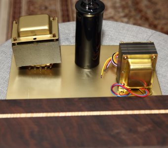
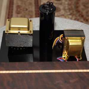
Did a quick color test a few days ago with a scrap of aluminum I had laying around.  Painted one side black and the other side with as close of a color match that I could find to brass (not ideal, but close).  Also used it to paint the bell on the PGP transformer.

I'm thinking black looks a bit nicer - there is a local guy who does powder coating, so I need to go visit with him for a little while.  Need to spend some time cutting and drilling first...
 

Attachments

  • Brass color base.JPG
    Brass color base.JPG
    545.7 KB · Views: 40
  • Black base.JPG
    Black base.JPG
    554.9 KB · Views: 37
I think they both look great. I'd be pleased with either.

cheers, Derek
 
I would always suggest a powder with a texture to it for these projects.  When you slip with your screwdriver installing hardware, those gloss powders are not going to be forgiving!  Gloss paints will be even worse than the powders. 
 
Good to know about scratching.  I suppose I had it in my head (honestly, I don't how half of the stuff up there got there in the first place...) that powder coating was somehow more resistant to scuffs and scrapes.  Now I can ask a better set of questions!

You guys rock - thank you!
 
My next task is choosing some wire.  I'd like to use different colors to signify heaters, B+, signal wires, etc. rather than having the chassis filled with with all black wire that I used on my prototype.  This part is easy - there are "standard" color charts floating around for wire color in tube amps.  It also seems there is a preference for solid core wire (20g) over stranded and the logic that solid core wires tend to stay put makes good sense to me.

So, this leaves me with what I consider to be an aesthetic choice for wire: teflon or cloth-over-pvc for the jacket.  To me, the cloth seems potentially more in line with "vintage" tube gear kind of look-and-feel.  With the options that I'm looking at, prices are close enough for either type to be considered equal, so price isn't really a decision factor.  The only thing that I can think of is that teflon might be easier and cleaner to work with than cloth. 

Is there something that I am missing that might suggest that this is not strictly an aesthetic issue?

Any impressions or experiences that might favor the use of either teflon or cloth?  Any value in choosing 18g instead of 20g?

Thank you!
 
The teflon covered wire will be impervious to heat from your solder iron, while the cloth on cloth covered wire can burn and also can soak up flux and end up looking unsightly.  Both are not the easiest types to strip.

You definitely want to use solid core wire.  Aside from the benefits you mentioned, there's only one strand to get to pass through each hole, while stranded wire tends to fan out if you try to pass it through small holes.  Once tinned, it will pass through OK, but then making a mechanical connection becomes more difficult.

I would stick with 20AWG for this project.  20AWG is listed with a maximum ampacity of 11A for chassis wiring, which is about ten times the maximum that you need.
 
Thanks, Paul!  This tips the scales toward teflon for me.  I'll get a color assortment from Steve at ApexJr.com.  I have a nice set of wire strippers that works well with teflon.  I use lots of CAT5 wire for projects and got tired of my old strippers nicking the wire and having it break all of the time, so I finally got a better tool.

I'm certainly no daVinci (who could probably still turn out a nice painting with a Wall-Mart brush), but having a proper tool tends to make certain tasks go more smoothly...
 
I got the Stripmaster that Doc has recommended a few times and it's been really useful for stripping teflon wire.
 
I had been using one of those "Self-Adjusting" automatic wire strippers (see image below) for a long time and it does an "ok" job, but it causes problems.  With smaller solid-core wire, it would often make nicks and with lager stranded wire, it often broke a few of the strands.  After putting up with it for years, I got tired of the problems.

Then, I purchased a Stripmaster for 16-26g wire.  It really works great! 
 

Attachments

  • wire stirpper.jpg
    wire stirpper.jpg
    7.4 KB · Views: 8
Stripmaster USA = $37  For me in the UK £96 Both Amazon.

Think I'll stick with the basic one I used for my Crack with no problems. I will be careful with the skinny Speedball wires!
 
EricS said:
I'll get a color assortment from Steve at ApexJr.com. 

+1 for Apex Jr (no affiliation). I'd never heard of them before. But after reading Eric's post I checked them out and ordered 200 ft of 20 awg teflon silver plated copper wire for $56 USD - 100 ft red, 100 ft black.  It just arrived. I'm no metallurgist, but after cutting it, stripping it and examining the gauge, it looks pretty good. It's unbranded. Judging by the couple of cuts I made, the silver plating looks to be substantial.  A good deal.

cheers, Derek
 
Good to hear!  I've bought tons of stuff from Steve over the past decade or so - never been disappointed.  I haven't put in my order for wire yet, been busy with work over the past few weeks.  I also need to visit my local metal guy and order some aluminum plates so I can start drilling holes and working out the mechanics. 
 
I've been exploring various resistors for trimming rectifier filament voltage and I came across a notation that I've never seen before.  For these resistors, the "Maximum Working Voltage" is listed in the data sheet as the square root of (3xR) - circled in red in the attachement.  If the ohmic value of the resistor is 0R05, does the mean that the maximum voltage that can be applied across the resistor is the square root of 3 * 0.05, or 0.387v ??

This seems VERY low for a 3w rated part.  I'm a little reluctant to put them somewhere where they are likely to see 450+ volts across them while the PSU comes up at power on.  Am I interpreting this correctly?  Something seems wrong to me...

Thanks for helping me understand!


Attachments

  • Voltage Rating.jpg
    Voltage Rating.jpg
    68.9 KB · Views: 17
Ohm's Law: current = volts / resistance = 0.387/0.05 = 7.74 amperes

Power is volts times amps = 0.387 * 7.74 = 3.0 watts

It's just another way of saying it's a 3-watt resistor. Your rectifier is not going to draw 7 amps, so no sweat.
 
EricS said:
I've been exploring various resistors for trimming rectifier filament voltage [...]  I'm a little reluctant to put them somewhere where they are likely to see 450+ volts across them while the PSU comes up at power on. 
Filament voltage is 5V.  You're using these to trim down a 5V supply.  They will not see 450V across them.  A 0.05 ohm resistor across a 450V power supply would dissipate 4 million watts ;)

(In reality your fuse will just vaporize instantly if you tried this)

 
Back
Top