You'd either have to ask PJ, or you'd have to buy one and try it out. It's still not the most optimal solution, as it puts out a regulated 6.3V, which we drop with a couple of low value resistors to get to 5V.
You are using an out of date browser. It may not display this or other websites correctly.
You should upgrade or use an alternative browser.
You should upgrade or use an alternative browser.
Need Help with First Tube Build - WE91 300B Parafeed Derivative
- Thread starter EricS
- Start date
EricS
Member
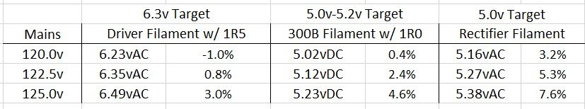
The mains voltages in my neighborhood seem to range from a low of 120v to a high of 125v, but seems to hang out most often in the 122-125 range. So, I used my variac to see what happens to filament voltage levels with mains voltages of 120v, 122.5v, and 125v. I can't seem to help myself, I'm a compulsive tweaker... ;D
I have a variety of datasheets and found lots of online discussions that talk about voltage tolerances for tube filaments for lots of tubes except the 5AR4 rectifier that I'm using. All of the datasheets I have found merely state 5.0v but I'm measuring more than that in my build. Does the "typical" window of +/- 10% apply here as well? Will the tube last longer in the long run with a +/- 5% window? My specific tubes are NOS Mullard f31 tubes.
I made a voltage chart and attached it below. Should I leave the rectifier heater as is, or is it better for the longevity of the tube to insert a 0R1 resistor in series that will bleed off 0v19 and shift the heater range down to 4.97v to 5.19v?
Thanks for the perspectives!
Attachments
D
Deke609
Guest
EricS said:... insert a 0R1 resistor in series that will bleed off 0v19 and shift the heater range down to 4.97v to 5.19v?
That's what I would do, assuming your measurements were taken with all tubes in place (power supply loaded). Then you'd be within 4% of spec.
cheers, Derek
EricS
Member
Derek: yep, completed amp at full temperature, all tubes lit and properly biased
Paul: I presume you are recommending the resistor in parallel to place a more "even" load on the AC filament? Does it achieve the same result if I put a smaller resistor in series with each side of the filament?
Guess I have a new round of experiments to try - I've been putting resistors in series with the filaments. At least resistors in parallel don't require a power down/cool down cycle for each value I try...
Yeah, you would be pulling the winding down a little bit, and the paralleled resistor would pull the voltage down less with lower line voltages and more with higher line voltages.EricS said:Paul: I presume you are recommending the resistor in parallel to place a more "even" load on the AC filament? Does it achieve the same result if I put a smaller resistor in series with each side of the filament?
I would snag a pile of 47 ohm 1W resistors and just clip lead them in parallel with the filament until you get the desired filament voltage.
EricS
Member
Ah - so resistors in parallel is a nice way to reduce the voltage variability a bit further... Cool trick!
I presume this works equally well for AC and DC voltages?
Each time I build an amp, I keep thinking to myself that I should start a new bound-paper notebook so that all of my notes stay together and in order. Then months/years later, I pick up some piece of paper and wonder "gee, which amp was this set of notes from???"
Sigh, I still haven't done this... Maybe now is a good time to start!
D
Deke609
Guest
That's what forum posts are for! ")
D
Deke609
Guest
@PB: Just for my edification: the parallel resistor approach will result in less current through the filament than the series approach, right? So depending on desired current draw of the filament, the series approach might work better is some circumstances, e.g., with some EML tubes? Or have I mixed up something basic?
cheers and thanks, Derek
cheers and thanks, Derek
EricS
Member
If I am understanding this correctly (I know, a little knowledge is sometimes dangerous...), both series and parallel resistors will help bleed off extra voltage, but the differences in physical arrangement will impact the voltage relationships.
The parallel approach will provide an extra measure of voltage "stabilization" or "buffering" by bleeding off less power (V^2/R) when mains are lower (slightly less voltage across resistor) and bleeding off more power when mains are higher (slightly more voltage across resistor). Thus, the magnitude of the mains-induced voltage swing at the filament will be reduced with parallel resistors.
Resistors in series with the current load of the filaments are more consistent in their voltage drop (current * resistance).
That is, if I'm conceptualizing all of this accurately ???
My guess is that the 5V winding you're using to heat your rectifier wants to see 3A of current draw (it could also be that it has a 115V primary, which is worth asking about), so adding a little extra draw with the resistors will pull the winding voltage closer to its specifications.
I do not usually recommend this approach for DC supplies, especially choke input filament supplies, as the regulation of the choke input supply will make this not work as well. You are also limited to the ratings of the chokes themselves, so if you have a 1.5A filament and a 2A choke, you can only pull an extra half an amp (DC) before you're out of gas. Doing this will also reduce the filter inductance a little bit, which is a negative side effect. Series resistance here is the more workable solution.
I do not usually recommend this approach for DC supplies, especially choke input filament supplies, as the regulation of the choke input supply will make this not work as well. You are also limited to the ratings of the chokes themselves, so if you have a 1.5A filament and a 2A choke, you can only pull an extra half an amp (DC) before you're out of gas. Doing this will also reduce the filter inductance a little bit, which is a negative side effect. Series resistance here is the more workable solution.
D
Deke609
Guest
Hmm. I misstated things in my previous post. I was remembering my tweaks to already existing series filament resistors in my SIIs and Kaiju where I decreased series resistance to get more voltage dropped across the filament. But here we're talking about adding series/parallel resistance, not decreasing it. So ... in this case I think: (1) adding series resistance will reduce current and split the voltage drop between the filament and the series resistor(s) - thereby reducing voltage across the fil; whereas (2) adding parallel resistance will increase current draw, and this increased current draw will drag down the voltage at the power supply, and in this way decrease the voltage dropped across the fil.
But maybe I'm still confusing things.
[Edit - PB posted while was I posting and cleared up my issue: adding current draw should bring down voltage of the heater power supply]
But maybe I'm still confusing things.
[Edit - PB posted while was I posting and cleared up my issue: adding current draw should bring down voltage of the heater power supply]
Paul Joppa
Moderator
Actually, the primary is designed for a nominal 117 volts 60Hz input and the 5v winding is specified at 2.0 amps RMS.
Hmm, so bring the 5V AC current right up to 2A (with a 50 ohm resistor in parallel with the filament) and call it good?Paul Joppa said:Actually, the primary is designed for a nominal 117 volts 60Hz input and the 5v winding is specified at 2.0 amps RMS.
EricS
Member
Paul Joppa said:Actually, the primary is designed for a nominal 117 volts 60Hz input and the 5v winding is specified at 2.0 amps RMS.
This is good to know! I wonder if there were different iterations of the PGP8.1 as I found a reference to 2.5v windings each being rated for 1.25A. Given my voltage levels under load, it appears the transformer does have 2A capability. A resistor in parallel it is!
Looks like it's time to turn focus toward the final chassis implementation...
Paul Joppa
Moderator
I should be clear that Mike LaFevre de-rated the windings to 2.0A at 6.3v and 1.25A at 5v - I have quoted the original spec of the design which came from Mike's vast collection from various "golden age" companies. Mike is often conservative about specs. It's a long story...
EricS
Member
Thanks for the details, Paul - this makes me feel better about pulling 1A9 for the rectifier out of the winding that is spec'd for 1A25 (at least on paper).
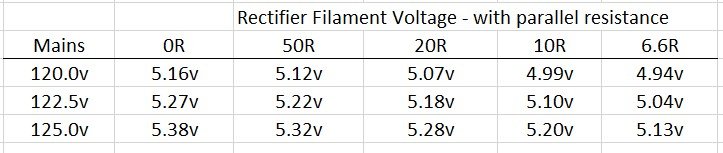
Playing around with various resistors in parallel with the rectifier filament, I'm inclined to think that this transformer can actually deliver a fair bit more than 2A on the 5v windings. I kept adding resistors in parallel until I got something in the voltage range that I liked. The best result was having 6R6 (three 20R 5w resistors) in parallel with the filament. This is an additional draw of 0A75! The increasing current draw didn't do very much to compress the range of voltages on the filament, but it did produce some pretty warm resistors.
I'm not sure that I'm comfortable pulling a total load of 2A65 on that pair of windings... I'll experiment with various resistance in series tomorrow. I'm thinking 0R1 or 0R2 might be sufficient to get the voltage where I want it.
Attachments
Paul Joppa
Moderator
The heat generated by a winding is proportional to the current squared. So 2.65A on a 2A winding makes nearly twice as much heat as the materials are rated for. It won't blow up immediately, but it very well might start a fire. It's a bad idea to exceed the rating. Don't do it!
Yeah, I would just take the improvement that the 50R resistor gives and not go any further.
Similar threads
- Replies
- 2
- Views
- 307
- Replies
- 45
- Views
- 1K