CCS Loaded Parafeed Output - Design Considerations?

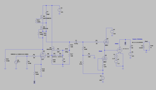
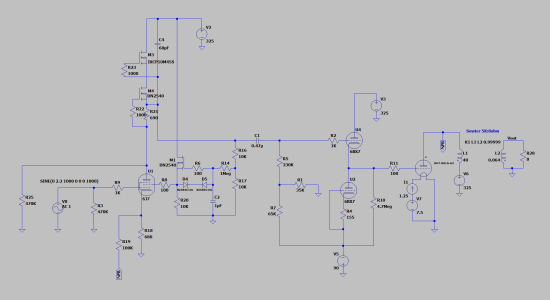
You can just use an adjustable bias pot to put either 0V or some amount of negative voltage under R5 to set the bias.  I wouldn't adjust the current on the cathode follower, just run it reasonably hard. 

Being a regulator type tube, you could use the other half of the BX7 as a series reg for your cathode follower and screen supply for the first stage.
 
Yeah just using a pot would simplify things wouldn't it.  That -100V supply will be shunt regulated so should work fine.  The 6BX7 current would be fixed by the current sink, was going to run it at around 90% plate dissipation, 325V plate-to-cathode at 28mA.

Thanks for the idea, the 325V B+ is regulated as well, but could definitely think of creative ways to use the second 6BX7 triode if I use two tubes.

Have you ever used cold cathode voltage regulator tubes like the VR105, PB?  I was going to experiment with using one on the screens of the pentode drivers.  The feedback circuit that is there now is a bit complex and I have seen some oscillation issues, but was recommended to avoid bias drift since the screen will track changes in plate voltage, although it hasn't been a big issue for me so far.
 
How much screen current are we even talking about? The LR8 is often recommended for low current apps like small pentode screens.
 
PB - Is this what you had in mind when using the other half of the 6BX7 as a series reg?

My 325 B+ is regulated, however it might be beneficial to drop some voltage across the other triode to run the cathode follower at a higher plate current.  Going over the datasheet, I see each triode has a 10W dissipation, but both together have a disappointing 12W, meaning using a single tube for both channels really hamstrings how far each cathode follower can be pushed with each at a 6W dissipation, only 18mA with a 325V B+.

Maybe I could set up a series reg with the other section and drop some voltage for a hot bias out of the knee of the curves on the cathode follower triode?  My other thought was to use two 6BX7 and parallel the two cathode follower triodes, both running at 325V 18mA (~6W a piece).

Here is the article that discusses the circuit below: https://electronicspost.com/series-triode-voltage-regulator/

As usual, thanks for your tube genius.
 

Attachments

  • Triode Regulator.png
    Triode Regulator.png
    40.8 KB · Views: 8
18mA is plenty.  You don't need to drop a ton of voltage across the regulator half, and I'd suspect you could do 9W/3W and get good results.
 
Gotcha, thanks again.  I'll think it over, either using a single 6BX7 with one triode per channel at 325V / 18mA at 6W dissipation, or use two 6BX7 with the series reg at something like 9W/3W.  The series reg is definitely cooler, if that counts for anything :)
 
I was reading through some old posts in this thread (gotten sort of long, hasn't it?).  Something caught my eye that probably didn't even register before: is one of your amplifiers based on the 3C24, PB?  I recently picked up a six pack of these tubes, along with a pair of HK54 (50W big brother), all pretty cheap as far as old triodes go.  I am getting my hands on a digital curve tracer very soon, thought I would trace them to find ideal operating points and think about building an amp with them some day.  Found some of those Eimac HR2 heat dissipating caps too, would need some sort of shield so the HV isn't exposed, I am thinking polycarbonate from a local plastics shop with holes for ventilation.  Working on this 801A design has been extremely educational, doesn't seem a far reach to build a 3C24 A2 design with the knowledge gained, maybe late 2021 or 2022.

The HK54 curves are sort of ridiculous, need to blow them up on a tracer.  Seems like all roads lead to transmitting tubes in this hobby.


Attachments

  • s-l1600 (2).jpg
    s-l1600 (2).jpg
    346.7 KB · Views: 7
  • s-l1600_2-2.jpg
    s-l1600_2-2.jpg
    706 KB · Views: 7
  • HK54_Curves.png
    HK54_Curves.png
    903.8 KB · Views: 8
Here is what I decided to do with the 6BX7, going to drop the FET current sink and use the other 6BX7 triode as the sink.  Since the bottom triode is only dropping 100V, can keep the total dissipation of the 6BX7 under 12W and push the top triode cathode follower to 20mA plate current, perhaps a little more.  Will come somewhat close to the heater-cathode limitations of the bottom triode (100V), will probably drop the bottom supply down to 90V which should still be fine for full grid swing of the 801A and will give a little more dropout headroom for the negative supply shunt reg.  One less PCB inside the chassis too and gets the heat out on top!


Attachments

  • 801A A2.png
    801A A2.png
    47.9 KB · Views: 10
So the reason I don't do that (there is a guy in Japan that does though!) is that the BX7 takes ages to warm up and the output tube does not, so the grid is just flapping in the wind.  This is why I tend to use a cathode choke or a resistive load under the DC cathode follower.  When you first fire up the amp, the output tube would see the full negative bias supply and have its own time to heat up before conducting.
 
Very good point, I figured there would be some issues with startup conditions but hadn't gotten into it yet.  Let me take another look at a choke or resistive load.  Another option - I have some time delay PCBs, relay switches after ~30s, can handle up to 500V.  I could put them between the B+ and OPT to allow the 6BX7 to come up before B+ is applied to the 801A.
 
I don't think that would be a problem.  The two triodes in parallel will let you use a lower resistor value, but will be somewhat demanding on that B- supply.
 
Yeah it would be demanding, always a compromise to be made.  I was planning on a TL431 shunt regulated B- supply, could probably spec it for 30-40mA.  I'm trying hard to use the 6BX7 since I have a bunch of them in pairs, but if it came to a point where I was using a single 6BX7 for both channels, I think it would make sense to switch to the 6AK4 or 6CK4 to take advantage of the higher single triode plate dissipation.  Also, maybe it is total tube amplifier voodoo, but in my experience I have found equivalent single-triodes to have better soundstage and imaging than equivalent dual triodes (6J5 vs 6SN7, for example), although I have not found a objectively measurable way to explain that (crosstalk, distortion, etc.).  Not sure if the same applies to cathode followers, haven't tried it yet.

I really like the second triode as a current sink if I can keep the 801A happy on startup, might really go with the time delay idea.
 
Hey PB - I'll check out the 12GN7, thanks.  I'm still brainstorming some ideas on the 6BX7 cathode follower feeding 801A startup biasing issue.

What about this - placing a high-value resistor between the 801A grid and negative supply.  At startup before the 6BX7 is biased, the 801A will see the full negative supply and be placed at cutoff, then the grid will rise to its 0V bias point as the 6BX7 come up to bias.

Any reason you can see that wouldn't work?  My thinking is this would also protect the 801A in the event of a failure of the 6BX7, although the 801A will be fused as well.  I might be making a mental error though, I am experiencing post night shift brain.
 

Attachments

  • 801A 6BX7.png
    801A 6BX7.png
    49.4 KB · Views: 8
Back
Top