Noisy sex

@Doc
The meter leads have been twisted since the first time you mentioned it.

@PB
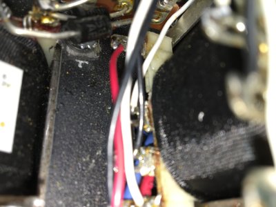
What points on the transformer would you like me to measure? What would be the ideal setup on the scope to take these measurements? How many V/Div would you like me to setup for? I'll take the measurements after work today.

@Grainger
The big reduction of the measurement came from a ground that I missed. Even though the measurement was reduced, it seems that the hum was barely reduced if any. I have my soldering iron (that wasn't powered on), and my oscope, both plugged into a rotel rlc900 line conditioner. I can unplug everything  and go straight to the wall if need be. When I first experienced the hum, I tried multiple outlets in my house, in two different line conditioners, I've also tried plugging into an isolation transformer, the hum was present no matter what.
 
I may have had my phone in my pocket, I don't remember 100%, for the most part it's basic test bench gear, or projects that I'm working on, but only the amp, scope, and soldering iron were plugged into the line conditioner at the time I took the measurements last night
 
The first two images are measurements taken before the resistors at the headphone jack, images 3 and 4 were after the resistor. I also would like to note that my scope was confirmed with a BK function generator. If any of my measurements or procedures need to be modified for more accurate measurements, please let me know.
 

Attachments

  • IMG_4127.jpg
    IMG_4127.jpg
    2 MB · Views: 77
  • IMG_4128.jpg
    IMG_4128.jpg
    2.1 MB · Views: 69
  • IMG_4129.jpg
    IMG_4129.jpg
    2.1 MB · Views: 79
  • IMG_4130.jpg
    IMG_4130.jpg
    2.1 MB · Views: 80
That looks familiar, if i'm not mistaken that 60hz base frequency is each half of the B+ voltage doubler circuit conducting.  Also from memory ~3mv was the natural noise floor of my amp so you may just be at the limit of the amp which is fine for speakers and less sensitive headphones. 
 
835 microvolts of noise is a completely reasonable noise floor for this amplifier.  Just for fun, take the probes off your amplifier, connect them together, then look at what' left on the scope  ;)

If you want to drag it down even more, put a 10 Ohm resistor between tip and ground and one between ring and ground in addition to your current resistor modification. 

These must be some very sensitive headphons!
 
I don't know the sensitivity of them off the top of my head, but just now, off of the Hi setting on the switch, I hear it in my HE500, AT R70X, Denon D5000, Denon MM400, HD598, B&W P7s, HD650s, and focal classics. The only ones where it was barely noticeable was on the Q701s, and Mad Dogs.

@PB
I only have one probe right now, I can get another one tomorrow. I'm going to order the 10R right now. What about the upgraded transformers, would they improve it? I also saw a modified power supply from a few months back, I think it's on page 7, titled Sex buzzing. I'm going to mock that up to try, I guess. It's just a shame that I went through a lot with this device, I hear people saying that they have black backgrounds, or they're using them with Grados, and so on. I'd do pretty much anything to get it silent. I even found a pair of mullard 6DN7s for it that weren't too cheap, hoping something positive would come from it :(
 
If you can hear it with HD650's on 4 or 8 ohms there is certainly something wrong, it should be dead silent with those.  I also own the HE500's which aren't especially sensitive either and should be silent on 4 ohms, the Grados however, they can hear a fly fart in the next room.

Point is, something still isn't right, but dont lose heart as the problem can be cured, we just need to find it first.    Without reading back through the pages, have you tried another set of tubes?
 
I have at least 4 pair. Rca that came with it, RCA coin base, Mullard, and GE's. I hear it on all of them. One of the coin base valves are a little noisy, I have another on the way. I'll buy anything I need to nail this issue down. I don't even know where to start to figure it out. I'll buy or borrow any tool needed. I've bought multiple valves, better pot, better caps, resistors, and diodes. It's just a little disheartening after all of the time and effort.
 
There is so much HF stuff on that waveform that it's very hard to tell what the actual 60/120Hz amplitude is. That 800uV average might be even lower with the fuzzy stuff cleaned off the test signal.

At this point it seem we might be at a the limit of what can be determined via the forum, as it seems like the amp is operating fine after all of this in terms of measurements. We don't have a way to tell if you are far more sensitive to hum than the typical person who builds this amp, if there is some other environmental interference issue that is unique to your environment, or if there is still something in the amp that is creating this issue (which doesn't seem likely after the fairly exhaustive testing you have done).

I think we are pretty much at a point where you need either another stock S.E.X. amp on your bench to compare to or to have someone else check the amp over to see if it is performing to spec.
 
@PB
I have a second probe. What would be the ideal setup for this? Just connect the ground clips and the hooks? AC or DC coupling? Do I have to invert anything or do any math functions with the scope?
What would I gain from upgraded transformers or chokes from MQ? Would they help with the noise?
 
RW said:
@PB
I have a second probe. What would be the ideal setup for this?
No need for a second probe. Take the prove you used for the photos, and clip the ground clip to the tip, then see what's left on your scope.
RW said:
What would I gain from upgraded transformers or chokes from MQ? Would they help with the noise?
You would lose the ability to switch between all the different impedances.
 
@Doc
that kind of stinks. Its definitely not me. I don't have the golden ear or anything special. It's clear as day on 80% of my headphones at the 4 ohm settings. I don't think I'll get a chance to compare and measure against another sex. I've read pretty much every page in this forum, I have some breadboarding to do. If all else fails, and I have no other avenues, I'll send it over to your team to look at, measure, and compare. I'll pay whatever charges there is. If your team says it is what it is, then I know I've tried everything I could.

@PB
here is a pic of the ground connected to the probe tip
 

Attachments

  • IMG_4136.jpg
    IMG_4136.jpg
    2.2 MB · Views: 82
The noise floor of your scope/probe setup is just barely below what you're measuring.  On your scope, is there an option to shelve off the high frequency hash?  (I think there is, I have an Owon scope that is similar to yours)
 
Do you know what this setting may be called? I'll look for it. the manual that came with the scope is hardly a detailed manual.
 
I'm sorry that I don't understand exactly what you think stinks. My point is simply that without hearing the amp ourselves we are limited in our ability to help by referring to the measurements that have been posted. If the amp was on my bench I could listen for myself with a familiar set of headphones, compare the noise floor to that of another S.E.X. amp as a point of reference, and possibly come up with some more ideas. As it is we are doing our best to help with something we can't experience first hand. Do try what PB is suggesting as that might give a cleaner picture of the noise floor in the hum frequency range.
 
@PB
The only setting that I was able to find was bandwidth limiting, which only limits to 20Mhz. I couldn't find anything in the manual, or the google regarding HF reject, or reduction. The photo shows the measurement of the probe with the ground clip connected to the lead, and the BW limiting engaged.

@Doc
what I meant by this kinda stinks, is that I/we worked a lot on this issue and that I may be stuck with this hum. It wasn't meant to be in any way offensive. As I mentioned above, If all else fails, I would be more than happy to send you the amp and pay all fees associated with the service. Your team, and this forum have been very helpful to me in all of my BH builds, and I appreciate everyone and all of their efforts. I apologize if my statement came off in a negitive way
 

Attachments

  • IMG_4138.jpg
    IMG_4138.jpg
    2.2 MB · Views: 145
This is a long shot, but easy to check:

In the very first post, RW said "-tried adding 100 ohm resistors in C1 & C2, to C3". The purpose of this is to keep the DC heater supply centered at ground potential. It assumes that C3 is grounded to the chassis, by way of the adjacent power transformer mounting screw, through the end bell, to the mounting screw nearest the power inlet, and from there to the safety ground adjacent to the power inlet. You can check the resistance from C3 to the chassis, which should be essentially zero. While you are there, power transformer terminal 10 (the heater winding center tap) is grounded to terminal 3, bolted to the chassis. Check that one as well, it should also be zero resistance (within the ability of your meter of course).

It's possible these checks were made; I did not review the entire thread today to check.
 
Hey PJ,
This may be the issue, or at least part of it. That terminal isn't grounded properly. I don't have any continuity from ground to the #3 lug. The only thing I can see that would be in the way is the fiber washers on either side of the plate, possibly? Because my plate is powder coated, I have the powder ground down to bare metal in all of the terminal, tube socket, and all screw locations. Should I remove the plastic washers and replace them with something else? Or, should I run a jumper from 3L to chassis ground?
 

Attachments

  • IMG_4139.jpg
    IMG_4139.jpg
    1.7 MB · Views: 166
It grounds through the power transformer cover, which may also have powder coating on both sides? 

If so, you can crank down on that mounting hardware and that may help your cause.
 
Back
Top