Yes, the output transformer secondaries will show continuity.RW said:This may sound like a silly question, but I'll ask anyway. Am I supposed to have continuity between all of the conductors on the output of the impedance switches, to the headphone jack?
You are using an out of date browser. It may not display this or other websites correctly.
You should upgrade or use an alternative browser.
You should upgrade or use an alternative browser.
Noisy sex
- Thread starter wink
- Start date
I think there is something in the way the measurement is being done that is throwing off the result, simply because 300mV of hum on the output would make the amp un-listenable. Your description is of hum that is there enough to bother you, but not something that completely overwhelms the music, so I will assume that the hum you are hearing is a couple orders of magnitude lower than 300mV.
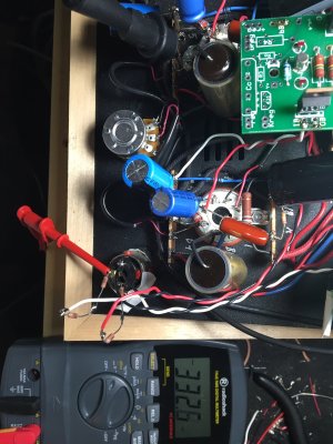
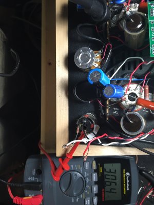
What we often find when trying to do AC measurements that that the test leads themselves can pick up stray hum. What I would suggest is to make that AC measurement again, with the red and black test leads twisted together (this helps to reject interference) and with the black test lead clipped to the negative terminal of the headphone jack, right next to the red test lead clipped to one of the positive headphone jack terminals.
What we often find when trying to do AC measurements that that the test leads themselves can pick up stray hum. What I would suggest is to make that AC measurement again, with the red and black test leads twisted together (this helps to reject interference) and with the black test lead clipped to the negative terminal of the headphone jack, right next to the red test lead clipped to one of the positive headphone jack terminals.
Hey Guys/Gals
So I need a little advice. What would be the best way to break this kit down in sections to isolate this hum? I've read just about every post in this forum, and the one solution that I haven't tried, which seemed to work for another member, was to rebuild the heater supply with a few 4700uf caps and a few resistors. I'm ordering parts to bread board it up, but I want to minimize the disassembly of the amp as much as possible, and I don't want to work on sections that are working fine? If I can't solve this hum, I'm just gonna drop the extra scratch and ship it over to the service dept to take a look at it.
Thanks")
So I need a little advice. What would be the best way to break this kit down in sections to isolate this hum? I've read just about every post in this forum, and the one solution that I haven't tried, which seemed to work for another member, was to rebuild the heater supply with a few 4700uf caps and a few resistors. I'm ordering parts to bread board it up, but I want to minimize the disassembly of the amp as much as possible, and I don't want to work on sections that are working fine? If I can't solve this hum, I'm just gonna drop the extra scratch and ship it over to the service dept to take a look at it.
Thanks
The first thing that you absolutely need to do is to get a better multimeter. The reading of 300mV of noise indicates that your meter can't resolve low AC voltages, so even if you could break the circuit down to isolate the noise, you can't measure it. If at all possible, take that one back to Radio Shack (FYI - the last six meters that I bought at RS were all defective)
Try the $25-ish multimeter from Harbor Freight, or borrow a different meter from a friend, then recheck the noise at the speaker posts/headphone jack. A very loud amount of noise in your application might be something like 10-30mV.
-PB
Try the $25-ish multimeter from Harbor Freight, or borrow a different meter from a friend, then recheck the noise at the speaker posts/headphone jack. A very loud amount of noise in your application might be something like 10-30mV.
-PB
Is the $25 HF meter going to be able to do what we need it to? If so, I'll have it tomorrow after work. Do I need something more accurate? Ill buy the $200 millivolt meter from MCM if need be. I also have an oscilloscope at my disposal right now. I'm not a pro with it but I can make it work. If there's something specific I need to do with it, just let me know and I'll do my best to make it happen.
As always, I appreciate your help
As always, I appreciate your help
I'm totally OK with helping you out while you use the scope, but the meter is a lot easier. I don't believe you'll need anything more accurate than that meter. I'll pick that particular one up on my way to work tomorrow and double check for you, just in case. The $200 meter is overkill, as in that case you'd want to move to your scope to have a look.
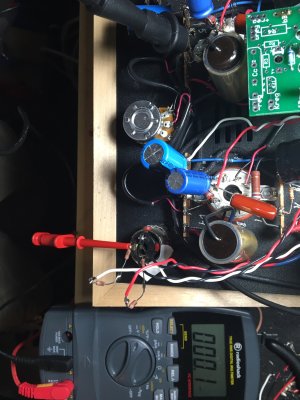
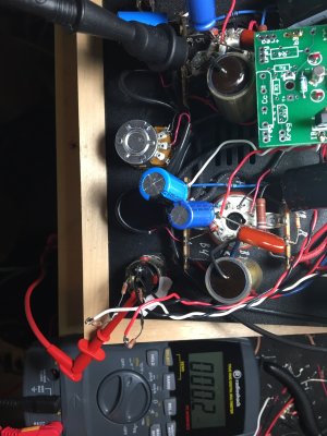
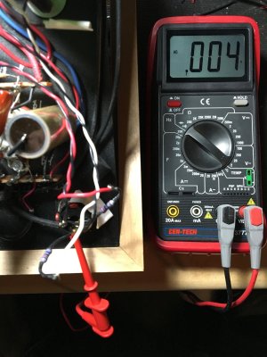
I tested our stock SEX (no C4S, no impedance switch kit) with the $25 HFT meter, it shows 0mV of noise on the 2V scale on the speaker taps on the 8 Ohm setting. It does seem to be able to resolve low AC voltages pretty well, so I'd say it's up for the task.
-PB
-PB
What noise figure do you get on the other side of that resistor on the headphone jack? (crank the volume pot all the way down too)
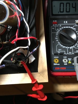
All output transformer measurements?RW said:Same, .004 on all switch positions.
I'd get out the scope at this point and post up a photo of what you see on the display.
Similar threads
- Replies
- 18
- Views
- 396
- Replies
- 0
- Views
- 276
- Replies
- 9
- Views
- 5K