Noisy sex

To go back over this, just to be sure I understand what is going on -

You are experiencing hum when using very sensitive headphones but not with less sensitive ones. The lowest impedance tap sounds the least hummy. That is all to be expected. 120 ohms in series did not reduce the hum further. That is not expected.

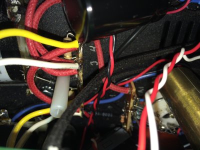
Could it be that the 120 ohm resistors were possibly not installed the way we intended? I say this because they were first suggested by PJ when I required the S.E.X. amp to be usable with sensitive headphones, specifically to lower the noise floor even more than the lowest impedance tap alone will. So the hum should be more quiet with the 120 ohm resistors in series with the outputs than without them in there. So just to verify, is each 120 ohm resistor in the hot (positive) leg of each channel? Basically one would break the connection of each red wire that goes from the impedance board POS pad to the headphone jack and solder a 120 ohm resistor into each break.
 
I took the resistors out last night to start putting all of the stock parts back in. The 120 ohm resistors were right at the headphone  jack, one was on the right lead, one on the left lead, nothing was on the neutral.
I didnt notice the hum until I put on a more sensitive headphone, now i know it's there, I can hear it on all of them.
I should have it finished and back to stock after work tonight. I Just have to finish wiring the RCAs and the pot. I'll take some measurements, take some photos, and report back.
Just for clarification, would you like for me to install the 120 ohm resistors again?
Thank you for your time and efforts, I certainly appreciate it :)
 
Also while your in there snap a pic of the wiring around the volume pot, i noticed you changed the audio path wiring, its important to have the shielding properly terminated as per the stock layout.
 
I am going to ask in this case that the community refrain from additional commentary for a bit so we (Bottlehead staff) can work through this methodically. Three or four different people suggesting three or four different things at once may serve to confuse things.

When you get it back together - with the 120 ohm resistors installed as you will need them for sensitive headphones - if you could check the following it would give us a good point at which to start with the redone circuit-

Is the hum constant regardless of volume control setting?
Is the hum a soft 60Hz, or is it buzzy?
Does it start the instant you turn on the power, or does it come on as the tubes warm up?

 
I added the shield ground to a terminal block. It followed the schematic, the stock terminal was too packed to fit it in so I added the screw strip and soldered everything there. I pulled it out last night to go completely stock again
 
Yes, for us to be able to offer useful suggestions regarding stock noise performance your taking the layout back to the  stock configuration will indeed be necessary. Rerouting or adding connections in the ground potential circuits seems like it wouldn't do any harm, but grounds are often not absolutely at zero potential and they can become a conduit for interference. The reason we are such sticklers about following the assembly instructions closely is that we have wrestled with these issues in many designs and the final layout we publish is the only one that we can post performance figures for with confidence.
 
No problem Doc, I totally understand. It's 90% back to stock. Once I get home from work, the other 10% will be finished. The only thing that I'm not wiring in is the speaker terminals. I just have to finish the input wiring to the pot. Once im done, I will post now photos. I'll also reinstall the 2 120 ohm resistors (2 60 ohm resistors in series)  on the headphone jack.
 
I finished getting everything back to stock and took measurements again. Every thing is within the 15% tollerance. The hum is still audible.

**note**
I couldn't find the solen 1.5uf caps. The ones installed are also 1.5uf at 630v
 

Attachments

  • image.jpg
    image.jpg
    1.8 MB · Views: 109
  • image.jpg
    image.jpg
    2.2 MB · Views: 96
  • image.jpg
    image.jpg
    2 MB · Views: 94
  • image.jpg
    image.jpg
    1.9 MB · Views: 103
  • image.jpg
    image.jpg
    1.6 MB · Views: 90
  • image.jpg
    image.jpg
    2 MB · Views: 92
  • image.jpg
    image.jpg
    2 MB · Views: 85
  • image.jpg
    image.jpg
    2 MB · Views: 92
  • image.jpg
    image.jpg
    1.6 MB · Views: 85
  • image.jpg
    image.jpg
    2.2 MB · Views: 106
OK, so now that we are back to stock and voltages check out, let's see if we can qualify the hum level a bit.

Is it just a soft deep hum - 60Hz - or is there a buzzy 120Hz component to it? If it is buzzy there might be a ground connection that is not quite 100%.

Is it present with less sensitive headphones with the 120 ohm resistors in place? Or is it just noticeable with sensitive headphones?

 
Soft 60hz hum for the most part. My least sensitive headphones (akg q701), with the impedance switches on low, I can barely hear it, but it's there. My 470 ohm r70x (highest impedance I own), I hear it on all switch positions. Everything I own in between I hear it on all switch positions as well.
 
OK, now put the 100 ohm resistors from C1 to C3 and from C2 to C3 back in, and see if that helps.
 
Just out of curiosity, can you measure the AC voltage from ground (on the headphone jack is fine) to the red and white wires that go to the headphone jack?  You'll likely need the mV scale to get a useful reading when taking this measurement.
 
My headphone jack isn't secure to th chassis right now because of disassembly.
If I put my neg probe on lug 13, I get around 350mv on the red and white.
 
RW said:
My headphone jack isn't secure to th chassis right now because of disassembly.
If I put my neg probe on lug 13, I get around 350mv on the red and white.
Hmm, are you sure it's not 0.3mV?  350mV would show as about 0.4V on a higher scale.

350mV is way, way higher than normal.  The immediate thing that comes to mind to cause this would be poorly connected power supply caps. 
 
I'll measure again. I'll be home in 30 min. Does it matter if I use safety, or signal ground when I take this measurement?
 
Signal ground is better.

300mV of signal on sensitive headphones would be audible from about 3 feet away, so do have a careful look at the units.

-PB
 
I just measured the headphone jack again. It's definitely 350 mv AC on my meter. I get .3 mv DC. Unfortunately my other meter doesn't read that low, so I can't confirm it.
 
This may sound like a silly question, but I'll ask anyway. Am I supposed to have continuity between all of the conductors on the output of the impedance switches, to the headphone jack? If I test the Jack and have one probe on black, I'll get continuity when I hit red or white. It doesn't matter what color I keep the probe on, the other two will beep when touched. Same with the impedance switches. If I keep one probe on the positive terminal of the impedance switch, I can hit the other 3 outputs and it will show continuity. But, headphones work fine. I'm looking at the schematic and I don't see where the two should cross (or four in this case)
 
RW said:
I just measured the headphone jack again. It's definitely 350 mv AC on my meter. I get .3 mv DC. Unfortunately my other meter doesn't read that low, so I can't confirm it.
Can you post a photo of your meter grabbing this reading?  It doesn't seem like a reliable measurement, as your sensitive headphones wouldn't handle that much voltage. 
 
Back
Top