The main practical difference between a soft start and the manual switch is the soft start resets itself vs. you have to remember to turn off the switch each time you shut the amp down. Bigger filter caps are fine, just be sure to heed the warning about voltage rating. They should be rated at least 600VDC.
You are using an out of date browser. It may not display this or other websites correctly.
You should upgrade or use an alternative browser.
You should upgrade or use an alternative browser.
New to me paraglow monoblocks
- Thread starter superchunk
- Start date
I have a Paraglow Manual here. I will work on making a copy.
Paul Joppa
Moderator
It's in italics because you first typed CTRL-I instead of SHIFT-I - at least, that's how I do it accidentally :^)Paul: I will start scanning it and when I'm done I will send it. feel free to remind me in a bit if I haven't. I do think it's probably cooler that you have it.
I will try...not sure why it's italics...to get those numbers tomorrow. Appreciate the help figuring out what I have.
Doc: yeah, I was using mute as a catch all sorts. right now it's wired to b+ and b- but no actual off abilities..
and I hear you on the 5965. all advice by you folks will be followed.
I like the idea of using DC link caps, as I'll be building the case to suit the build. Any thoughts on upsizing to maybe 200uf each? I am a believer in ps capacitance in general...would that help here, and would I need to be concerned about inrush beyond the b+ switch? perhaps soft start needed too?
A scan is fine - whatever is easiest.
The soft start is not necessary, because the driver plate voltage is taken from the 2A3 cathode. That makes a semi-soft start of sorts.
superchunk
New member
It's in italics because you first typed CTRL-I instead of SHIFT-I - at least, that's how I do it accidentally :^)
A scan is fine - whatever is easiest.
The soft start is not necessary, because the driver plate voltage is taken from the 2A3 cathode. That makes a semi-soft start of sorts.
I would give you the original and I'll keep the scan for myself. Not sure if Eric has one for you instead? Happy to send you the original if not.
tsingle999
Member
Those are pretty cool looking pieces of history. I am glad you like the sound! I am way out of my league here compared to the other suggestions but I have a couple if they even apply to your amp. I have found MQ grid chokes to improve the sound quality if you can place them where they don't pick up noise. I have also like the sound quality improvements in replacing the cathode cap with a film cap like a Panasonic DC link film cap.
superchunk
New member
superchunk
New member
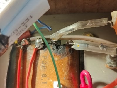
oof...that doesn't look good. they sound so good I'm a bit surprised to see burns...
Is this garbage, unsafe? what do y'all think happened here?
What's the AC voltage between those terminals?
superchunk
New member
What's the AC voltage between those terminals
What's the AC voltage between those terminals?
558
What are the DC voltages on each pin of the 2A3 in that amp?
superchunk
New member
What are the DC voltages on each pin of the 2A3 in that amp?
I get:
1. cathode 146
2. plate 428
3. grid 92
4. cathode 146
Paul Joppa
Moderator
Those terminals would be labeled 1F and 1S (left to right) if I am correct. That would be the finish and start of the high voltage winding; the tap 1T is opposite 1F on the opposite end of the winding. That suggests this may be arcing, though burning by a misplaced soldering iron is also a possibility. The voltages look good.
The PGP8.1 has been out of production for a long time now, and a replacement would be difficult to find. You may have to live with this for a while. I have no expertise with repair of power transformers so I hesitate to suggest more than cleaning it up gently.
The PGP8.1 has been out of production for a long time now, and a replacement would be difficult to find. You may have to live with this for a while. I have no expertise with repair of power transformers so I hesitate to suggest more than cleaning it up gently.
Last edited:
superchunk
New member
Those terminals would be labeled 1F and 1S (left to right) if I am correct. That would be the finish and start of the high voltage winding; the tap 1T is opposite 1F on the opposite end of the winding. That suggests this may be arcing, though burning by a misplaced soldering iron is also a possibility. The voltages look good enough to say that it's not leaking very much now, but it does make you worry.
The PGP8.1 has been out of production for a long time now, and a replacement would be difficult to find. You may have to live with this for a while. I have no expertise with repair of power transformers so I hesitate to suggest more than cleaning it up gently.
Hmm, yeah kind of a bummer. I suppose I could have a couple of new ones made to spec at some point. I should start looking into not that I suppose don't want to wait for issues to arise.
I'd agree with PJ that is was either a careless soldering iron, or maybe some debris that got lodged between those terminals temporarily and burned off. I would get some Q-tips and alcohol and try to clean that off gently if you can, but since the voltages are OK, it's not an enormous concern. (what is a concern is that there's carbon there trying to connect the two terminals).
superchunk
New member
ah yes, I see why that would be a concern, I'll clean it up best I can.
I'm general the wiring kinda freaks me out on these, the first one I took out was two wires soldered together behind unshrink heatshrink, barely holding on that just fell apart when I touched them. I was going to look to do everything at once in the future but I think I should be working on rewiring ASAP.
I'm general the wiring kinda freaks me out on these, the first one I took out was two wires soldered together behind unshrink heatshrink, barely holding on that just fell apart when I touched them. I was going to look to do everything at once in the future but I think I should be working on rewiring ASAP.
superchunk
New member
ok so, I ordered 4 x 100uf wima dc link caps, and am ordering some new resistors to increase the voltage to the 2a3 and drivers a bit.
Just want to run it by the experts before buying. I will then rewire everything, new caps etc...
New resistors:
- cathode resistor to 900ohm - 10w ww - use 4x 910 10w I. series/parallel to get 910 40w
- drop resistor b - 1.2k 10w ww
Just want to run it by the experts before buying. I will then rewire everything, new caps etc...
New resistors:
- cathode resistor to 900ohm - 10w ww - use 4x 910 10w I. series/parallel to get 910 40w
- drop resistor b - 1.2k 10w ww
superchunk
New member
So I've ordered some parts and about to order the rest and hopefully finish the rebuild in the next few weeks.
I had llm help me organize my thoughts and understand a few things and this is the summary of changes I intend to make it would be awesome if someone could review and make sure I haven't made any mistakes.
Project Goal: Optimize for PGP 8 Power Transformer and 3W output target for 500Hz+ midrange operation.
I. Component Value Changes
Driver Cathode: Changed from 274 ohm to 180 ohm (Increases 5965 current to ~10mA).
C4S Board R1: Changed from 237 ohm to 150 ohm (Sets C4S current to match 10mA target).
2A3 Cathode: Fixed at 3k ohm (Two 1.5k ohm Mills MRA-12 in series).
Main Dropper Resistor: Changed from 1k ohm to 2.2k ohm Mills MRA-12.
C4S Protection (New): Added 15k ohm 12W Mills resistor between supply rail and C4S input to pre-drop voltage.
Grid Stopper: Changed from 1k ohm to 681 ohm.
II. Topological & Wiring Changes
Driver Power Feed: Driver stage is fed directly from the power supply rail (after 2.2k dropper) rather than being tapped from the 2A3 cathode.
Standby Implementation: SPST toggle switch breaking the High-Voltage Center Tap to Ground. A 100k ohm 2W resistor is wired across the switch lugs.
Power Supply Filter: CLC configuration using DC Link Capacitors. Each cap is bypassed with a 0.1uF high-quality film capacitor.
AC Input Snubber: 1 ohm 10W Mills MRA-12 + 0.1uF X2-rated Safety Capacitor at the IEC inlet.
Rectification: Solid-state Schottky diode bridge.
III. Hardware Specification
Output Transformer: MagneQuest Cobalt.
Parafeed Capacitor: 6.8uF Mundorf Silver Gold Oil.
Parafeed Connection: Transformer -> Cap -> Signal Ground.
IV. Design Questions for Review
Given the PGP 8 and Schottky rectification will likely yield a B+ rail near 425V–435V, is the 3k ohm 2A3 cathode resistor sufficient to keep plate dissipation within safe limits?
Does the use of the 15k ohm pre-drop resistor properly resolve the thermal load concerns for the C4S transistors in this direct-feed configuration?
Are there any concerns regarding the 6.8uF parafeed value relative to the MagneQuest Cobalt inductance when used strictly for 500Hz+ midrange reproduction?
For what it's worth, I remove the standby switch from every vintage Bottlehead kit I take in for repair. Assuming you forget to open the standby switch and you turn the amp on, if you have the driver B+ being fed from the high voltage rail rather than the 2A3 cathode, you will have the grid of the 2A3 biased up to +400V, which is no bueno.II. Topological & Wiring Changes
Driver Power Feed: Driver stage is fed directly from the power supply rail (after 2.2k dropper) rather than being tapped from the 2A3 cathode.
Given the PGP 8 and Schottky rectification will likely yield a B+ rail near 425V–435V, is the 3k ohm 2A3 cathode resistor sufficient to keep plate dissipation within safe limits?
Likewise, I think you'd struggle to measure the difference in B+ between Schottky diodes and UF-4007 diodes.
The 2A3 plate dissipation is controlled by the driver stage plate voltage primarily. I've gone back into some of my older directly coupled 2A3 Bottlehead amps and added the Kaiju driver stage bias adjustment so the plate voltage can be dialed in for ideal 2A3 plate current.
superchunk
New member
roger, so simple on/off...(mine currently has an on/standby with no off).
it seems to me the stereomour 2 shunt upgrade kit would work as the paraglow is similar setup?
it seems to me the stereomour 2 shunt upgrade kit would work as the paraglow is similar setup?
Paul Joppa
Moderator
OK, here's your reminder :^)Paul: I will start scanning it and when I'm done I will send it. feel free to remind me in a bit if I haven't. I do think it's probably cooler that you have it.
I will try...not sure why it's italics...to get those numbers tomorrow. Appreciate the help figuring out what I have.
Doc: yeah, I was using mute as a catch all sorts. right now it's wired to b+ and b- but no actual off abilities..
and I hear you on the 5965. all advice by you folks will be followed.
I like the idea of using DC link caps, as I'll be building the case to suit the build. Any thoughts on upsizing to maybe 200uf each? I am a believer in ps capacitance in general...would that help here, and would I need to be concerned about inrush beyond the b+ switch? perhaps soft start needed too?
I'll post again shortly with notes on the changes.
Similar threads
- Replies
- 47
- Views
- 2K
- Replies
- 9
- Views
- 6K