You are using an out of date browser. It may not display this or other websites correctly.
You should upgrade or use an alternative browser.
You should upgrade or use an alternative browser.
New Crack build.
- Thread starter richmi
- Start date
Grainger49
New member
Richard, I found it and bookmarked it. Thanks!
Here is a tip from the old board.
You do not have to buy 4 Cree diodes, just one. They cost dollars not cents.
Put it in series with the B+ (high voltage) anywhere in the power supply. That is after the + of the first four diodes, before/after the first cast resistor, before/after the second cast resistor or as the B+ leaves the terminal strip going to the 6080.
It removes the Reverse Recovery Spike that the stock diode string puts into the power supply.
This is the Cree part number that I used:
CSD01060A
I went for this upgrade after reading this post by Paul Joppa where he says that it probably would make more difference than bypassing a filter capacitor. Please, keep in mind that this post applies specifically to the Smack headphone amplifier that is now a legacy product.
http://bottlehead.com/smf/index.php?topic=4258.msg39230#msg39230
I read somewhere a post by PB saying this part would work in the Crack circuit, but I can't find it right now.
Richard
i luvmusic 2
New member
I'am interested with this MOD i have two questions.
1. Which Cree diode did you used from Partsconnexion?
2. Will this work for the SEX?
Thanks!
1. Which Cree diode did you used from Partsconnexion?
2. Will this work for the SEX?
Thanks!
The Cree diode part number is:
CSD01060A
http://www.partsconnexion.com/product7559.html
You can also get it from Mouser, Digikey, Newark and other suppliers.
and the PCB is here:
http://www.partsconnexion.com/product26996.html
As to whether you can use this mod in the Sex, you would have to ask the specialists.
Richard
CSD01060A
http://www.partsconnexion.com/product7559.html
You can also get it from Mouser, Digikey, Newark and other suppliers.
and the PCB is here:
http://www.partsconnexion.com/product26996.html
As to whether you can use this mod in the Sex, you would have to ask the specialists.
Richard
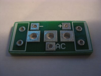
Negative. (The board is the incorrect configuration)i luvmusic 2 said:2. Will this work for the SEX?
lth1
New member
First, parts connection is the last place you want to purchase cree schottky diodes, I usually use Mouser or Digi-Key, last purchase was $2.08 for 2A 1200V. I used 1 amp 600V in my crack (Paul (PB) said the 600V cree was OK in the Crack), but normally use 1 or 2 amp 1200V. The parts connections PCB are really easy to install, I did not use standoffs just 20 or 18 gage teflon wire and let the PCB float.
Paul Joppa
Moderator
To expand on PB's terse note, the 600v diode should work in the SEX voltage doubler, since it works in the higher-voltage Paramount doubler. Whether you can physically connect it may be a more complicated and difficult question, since the Crees have short PC board mounting leads and the SEX uses the long leads on the UF4007s to connect between different terminal strips.
mcandmar
New member
I can confirm the Cree's dont physically fit into the S.E.X. as the terminal strips are too far apart. Having said that i did manage to fit them into mine by extending the legs and insulating both the legs and main body to prevent shorts, but i dont recommend that setup to anybody.
The best solution is to have some small PCB's made up for voltage doubler configuration. Unfortunately i dont have any left before anyone asks.
The best solution is to have some small PCB's made up for voltage doubler configuration. Unfortunately i dont have any left before anyone asks.
Attachments
Grainger49
New member
Adding to Lee's post. I searched Mouser and DigiKey for the part number. It is $1.02 at both.
http://www.mouser.com/ProductDetail/Cree-Inc/CSD01060A/?qs=%2fha2pyFaduha8e7L7P6H8AQPAaWzRYR18hPNYjU5%252bzc%3d
http://www.digikey.com/product-search/en?x=21&y=17&lang=en&site=us&keywords=CSD01060A
DigiKey has a first class mail option for shipping.
http://www.mouser.com/ProductDetail/Cree-Inc/CSD01060A/?qs=%2fha2pyFaduha8e7L7P6H8AQPAaWzRYR18hPNYjU5%252bzc%3d
http://www.digikey.com/product-search/en?x=21&y=17&lang=en&site=us&keywords=CSD01060A
DigiKey has a first class mail option for shipping.
i luvmusic 2
New member
Got it THANKS ALL!
ATM i ordered from Parts connexion it's 30mins. away from where i work.")
THANKS!
ATM i ordered from Parts connexion it's 30mins. away from where i work.
THANKS!
i luvmusic 2
New member
Holy Crap! I bypass the last 220uf cap with a SOLEN 2.2uf and i was surprised how it changes the sound it add a little to the treble.
Grainger49
New member
Bottlehead uses top notch parts that won't cost an arm and a leg. Then leave the tweaking up to us.
I'm not surprised at your reaction.
I'm not surprised at your reaction.
i luvmusic 2
New member
I didn't expect the changes because the cap is on PS side but wow, i'am liking it with the HD 650 but not so much for the DT880 600 ohms it's a bit bright.Now i can't wait for the diodes that i ordered what that thing would bring up.
Paul Joppa
Moderator
The signal current through the headphones also flows through the power supply (mostly the last capacitor) and the output coupling cap.
i luvmusic 2
New member
Good to know thanks.
i luvmusic 2
New member
Can anyone please tell me if the way i'am installing the CREE BOARD is right.
Looking at Richard's Cree Board picture i can't tell where the + and - leads from the Cree board connected to but i check the crack manual and i think + from the Cree board connect to T21 and - from Cree Board connect to T20 is this correct?

I will remove all of the Diodes from the CRACK and T18(Black Wire) connect to Cree Board Solder Pod bellow D3 and T19(Red Wire) connect to Solder Pod bellow D2 is this right(Referred to Richard's Picture,Thanks Richard).
THANKS!

Looking at Richard's Cree Board picture i can't tell where the + and - leads from the Cree board connected to but i check the crack manual and i think + from the Cree board connect to T21 and - from Cree Board connect to T20 is this correct?
I will remove all of the Diodes from the CRACK and T18(Black Wire) connect to Cree Board Solder Pod bellow D3 and T19(Red Wire) connect to Solder Pod bellow D2 is this right(Referred to Richard's Picture,Thanks Richard).
THANKS!
i luvmusic 2
New member
I already soldered the Diodes on the PCB however i can't find a small nylon standoff locally.
What is the size of the standoff you used?
Thanks You!
What is the size of the standoff you used?
Thanks You!
Similar threads
- Replies
- 50
- Views
- 1K
- Replies
- 24
- Views
- 779
- Replies
- 6
- Views
- 196