You are using an out of date browser. It may not display this or other websites correctly.
You should upgrade or use an alternative browser.
You should upgrade or use an alternative browser.
Bottlehead style nixie clock build log
- Thread starter phatfish
- Start date

Karl5150
Member
Phatfish lit the fire to get me cooking on this one.
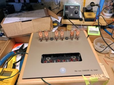
I ended up going the lazy (read expensive) route and had Front Panel Express produce the panel. The 10x10 format leaves lots of room under the hood - my plan is to use some rechargeable 12V battery packs to cut the cord.
I was a little unsure of my choice to mount the motion sensor front and center on the panel, but it works a treat. Should help the tubes last and eventually keep the recharging sessions to a minimum. (Unless the cat figures out how to keep it lit for his own nefarious purposes)
Attachments
Karl5150
Member
Thanks Phatfish, the wife is also pleased with how it turned out, so bonus points there.
FPE calls the color Medium Bronze. What I see on the monitor is very close to the actual color and champaign is probably more accurate.
Some kind of a plastic shield is probably a good idea. That said, I have a PCB based tube phono stage I built with the same form-factor that I have been using for almost 5 years with no issues, although the clock is more accessible to curious fingers when the grandkids visit.
Setting the clock: At the risk of perpetuating the double entendre associated with the BH naming convention, with everything in the stock configuration, I just reached up under the skirt and fiddled with the button(s) until the desired outcome was achieved.
Karl