Need Help with First Tube Build - WE91 300B Parafeed Derivative

Hmmm...  I was thinking a meter would be a good way to keep an eye out for aging tubes and a situation like the one I just ran across with what appears to be a bum tube.  Rather than connecting the meter to the plates as I indicated above (and the accompanying high voltage), I was thinking of connecting it across the cathode resistors.  Thus the meter would see ~70v on the output tube and ~60v on the driver tube.  With a 1/2Meg resistor attached to the PSU bleeder, there would be less than 50v there as well.  I thought installing a meter would be easier and safer than periodically attaching DMMs to the inside of the chassis to see how things are going.

Is this a better plan? Or is adding a meter just a bad idea in general?


EricS said:
Hmmm...  I was thinking a meter would be a good way to keep an eye out for aging tubes and a situation like the one I just ran across with what appears to be a bum tube. 
With a cathode biased amp, the difference between a strong 300B and a weak 300B is really hard to resolve with a panel meter.  It might be a difference of only a couple of volts, and of course the AC wall voltage has to be considered as well.

EricS said:
I thought installing a meter would be easier and safer than periodically attaching DMMs to the inside of the chassis to see how things are going.
That is something that folks generally do when something isn't going well.  If you're curious about the condition of your 300Bs, keep a spare set handy and plug them in every year or two to see if they sound remarkably better than what you're running.

EricS said:
Is this a better plan? Or is adding a meter just a bad idea in general?
Meters are super cool and very helpful when you have adjustable bias, but everything in this design will automatically bias.  If you want to add them for the sake of appearance, that's a great reason to have them!  If you decided to build a fixed bias 300B amp instead of a cathode biased 300B amp, then meters would be very useful. 
 
I see - thank you for your patience with me and for providing the additional details, Paul.  All are much appreciated!  I didn't realize the meter would be so ineffective with a cathode biased amp - I suppose the discussions I found online were in the context of fixed bias amps without explicitly stating so.

Back to my previous problem of the 6SJ7 driver tube not biasing up properly, I've been through four different tubes.  All exhibited EXACTLY the same behavior.  I'm thinking the problem is not the tube.  I double checked the tube socket wiring and haven't found any errors.

I'm now working on changing out the cathode bypass caps.  These, too, are NOS parts - Russian OKGB tinfoil, paper, and oil caps, though they've been tested prior to assembly.  I am using two 8uF 200v caps in parallel.  I tested them for leakage at 180vDC with my cap leakage meter and they exhibit no measurable leakage on a 50uA scale meter.  They also measure proper capacitance on my LCR meter.  But I'm changing them out anyhow for some modern poly caps just to remove a variable.

I'm not sure what to check next.  At least the schematic is pretty simple, so there aren't too many things to check...   
 
This is reminding me of some frustration when attempting to deal with the loctal equivalent of the 6SJ7.  It could potentially be that the SJ7's curves are specified for 0V on the suppressor grid, but I ended up using a different tube and not taking the time to determine if that was causing the problems I was having.  Are all of your tubes showing about 220V on the plate and 100V at the screen?

Probably the easiest change to make would be a slightly lower cathode resistor, as changing the plate load or the screen voltage will make a not so subtle operational difference, but nudging down the cathode resistor won't because it is bypassed. 

As always PJ will know what to do!
 
Interesting...  I changed out the R6 + C5 combination and tried a 5th tube with exactly the same results.  I haven't measured each of the 6SJ7 pins for voltage relative to ground.  I'll do that next, perhaps it will provide some additional clues.

Unless there is some really obvious error I have made that I just can't see right now, my next thought was to start playing with resistor values...

 
Looking back at Paul's notes concerning R6 - he did indicate the possibility of having to adjust this value in order to hit a target of 170v for the plate and that +/-20v would be sufficient.  Figuring he meant this more as a "minor tweak" I ordered 1k1, 1k2, and 1k3 values.  I'll swap 1k2 for 1k3 and see what happens... 
 
Since you have the appropriate plywood mockup, you could also get a 5K pot and wire it up as a variable resistor.  Start with it all the way up at 5K, then turn it down till you see the desired plate voltage.

Power down and repeat for every 6SJ7 tube that you have, then adjust the value til you reach a sensible average for the sample of tubes that you have.
 
Ha - We were thinking exactly the same thing!  As I was sitting on the couch last night at 11p watching an old Hitchcock on TCM and fighting off the urge to power up the soldering iron again, I starting thinking about the pile of 1K and 5K trim pots that I have laying around for my solid state builds.  A few extension wires, a dab or two of solder, and I'll be able to experiment!  But I figured if I started at 11p, I'd never get to bed...

I like the idea of averaging for the sample of tubes that I have - I wouldn't have thought of this.  The rest of the circuit has been stable enough over the few hours that I've been playing around that I'm confident enough to hook up an old test speaker and run some music through it tonight or tomorrow.  Tonight is "movie night" with the kids in our theater (see my homepage link), so I'm not sure if I'll have the time to get to it or not...

Looks like it might soon be time to turn my attention back to the chassis.  I'm trying to figure out a parts layout and "sub-structures" below the top plate for mounting components that minimizes the "Chicken Pox" look of a million screw heads piercing the top plate.
 
A builder here had the same visual disdain for lots of screw holes, so he ended up making an extra top plate that sat on top of the normal top plate to cover them all up. 

If you paint/powder coat your chassis black and use black screws, they will tend to disappear, or you could maintain the plywood style of build and mount everything to the bottom plate, then let the tubes and iron stick up!
 
I'm torn between doing black powder coat on aluminum or using brass to match those nice TFA-2004 bells.  Of course, they would REALLY stand on a black background.

Here is the wood that will be used for the chassis frame.  It's some nice cross-grain figured walnut that I found at the local flea market.  I split it and added a 1/4" stripe of tiger-striped maple.  There are three boards in the image.  From top to bottom are the rough glue-up, the middle one has the layers sanded smooth, and the third one is after applying a coat of pure Tung Oil, allowing it to soak in a for a few days, then top-coating it with some Formby's Tung Oil Finish (which I'm not sure if it actually contains Tung Oil or not).  I tend to like darker wood.  Still undecided, though, about that top plate  :-\


Attachments

  • Chassis Frame.JPG
    Chassis Frame.JPG
    349.7 KB · Views: 26
Wow. That is some beautiful wood. Nice inlay work. My vote would be for black powdercoat and black anodized screws/bolts.  But you might also try brass screws/bolts - they might actually look nice with a black chassis and the brass end bells.  Or go with black everywhere except brass on the on-top OTs or chokes (I don't remember which is going on top in your build).


That amp is going to look (and presumably sound - since PJ designed it) great!


cheers, Derek
 
The only parts visible from the top will be the three PSU caps (black), the PGP8.1 (bell painted and lacquered to match brass), the TFA-2004 output transformer (actual brass bells), and the three tubes.  Of course, the usual fair of input/output jacks, power switch, fusing, etc. will also be on top.  Everything else will be hidden below deck.  I'm thinking I will need to cut some slots for airflow around those big power resistors - they will be mounted directly to the underside of the top plate with a little thermal paste for good heat transfer.
 
OK - now I'm totally confused.  I installed a 5k pot in place of the 1k2 resistor at R6 and made some voltage readings across the pot as I adjusted it.  As I adjusted the pot toward 0 ohms, the voltage across the pot (R6) fell.  At the same time, the screen voltage on Pin 6 between R8 and R7 also fell, to about 80v (was 100v with 1k2 resistor in R6).  I was expecting exactly the opposite..

Looking to achieve something closer to 60v across the pot (leaving the 170v target on the plate), I adjusted the pot toward 5k  and the voltage across it started climbing.  With the pot maxed out at 5k, the voltage across it increased to only 5.5vDC.  With a value of 5k in the R6 position, the driver screen voltage rose from its previous 100v to 110vDC. 

I was sure using a pot would solve this problem, but it didn't.  Any ideas??
 
Here's what I think is happening with the screen voltage -


With the pot at 0 ohms, the tube turns on harder, drawing more current, which then pulls the B+ voltage lower. Since the screen node is a voltage divided version of B+, it also drops. With the pot at 5K ohms, the opposite happens. Can you confirm all this by monitoring B+ as you vary the pot?
 
Thanks for the suggestion, Raymond.  Attached is a chart of various resistances at R6 and resulting B+ and voltages at the divider for the driver screen voltage.  The asterisk at 1200R is the original value from the schematic. 

I attached an old speaker and my iPad for the first time today and it makes music!  Woohoo!  It sounds good to me - only a single channel on an old speaker, but there is no obvious audio distortion or other distress that I could detect.  With the hum pot adjusted for 0.0mV AC at the speaker terminal, I can hear a faint hum from the woofer with my ear next to it.  The woofer was silent when I connected the 10,000uF cap across the heater.  The speaker output volume gets to about where I expected it would with ~8w of output from an underpowered input (max line level output on apple devices always seems low to me in the context of CD player/DAC output).  It sounds like the amp is functioning properly.  The only issue is that voltage measurement across R6.

Edit: the 6SJ7GT datasheet indicates a maximum plate voltage of 250v and a maximum screen voltage of 125v, so I don't think the amp or tubes are in danger with the 1200R in place for R6.  I've also attached a more complete voltage chart on the schematic.
 

Attachments

  • Schematic 300B - Voltage Map Aug 31 2019.jpg
    Schematic 300B - Voltage Map Aug 31 2019.jpg
    156.7 KB · Views: 14
  • R6 Resistance Chart.jpg
    R6 Resistance Chart.jpg
    61.5 KB · Views: 12
Doesn't look like there's significant change in B+ voltage to account for the screen voltage change. It looks like R6 varies the amount of current into the screen grid though (the difference in current through R8 and R7). I wonder where that current ultimately flows to, as it doesn't seen to be going out of any of the other pins of the 6SJ7.

Despite the mysteries, it's great your amp is working!
 
Looking at the schematic again and the associated voltage drops that appear between B+ and Ground in the driver circuit, adjusting R6 seems to have little impact on achieving the 170v target plate voltage.

Total noob question here:
Is there any immediate danger associated with me adjusting the 91k value of R9?  If I increased the resistance of R9 to something larger than 91k, would it drop more voltage, thereby decreasing the plate voltage and allow more voltage to develop across R6?

Does this sound reasonable, or am I missing something fundamental here...
 
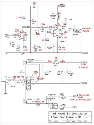
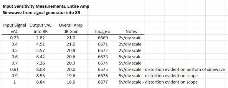
I spent some time making measurements with some meters, a signal generator, and scope with the hopes that someone can either guide me toward making a change to elevate the driver cathode/adjust the plate voltage to the intended voltage, or just leave it alone and start enjoying the amp.  Overall, the amp with the PSVane 300B tube can drive about 8v into an 8R load with an input signal of 0.8vAC before distortion becomes evident on the scope.

Here is a description of the tables I've attached:

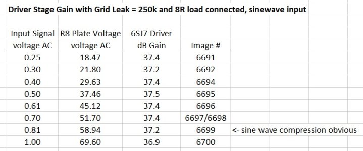
The first attached chart is gain measurements of the 6SJ7GT driver stage, measured at the "input side" of the coupling cap with an 8R load attached.  Looks pretty constant at about 37dB of gain for the first stage.  Don't know if this is where it is supposed to be or not...

The second chart is the overall gain of the entire amplifier into an 8R load as well as input signal level sensitivity. Overall gain for the entire amp into an 8R load looks pretty constant at about 21dB.  This seems a little low to me, I was expecting somewhere closer to 27dB based on some comments PJ posted some time ago on another forum.  It also took close to 0.75vAC input in order for the amp to reach maximum clean output on the scope.  PJ's prior posting also indicated an input sensitivity of about 0.35vAC, so this figure looks a little "off" to me...

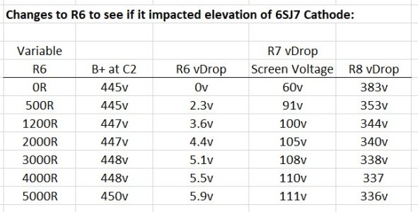
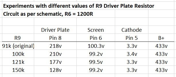
The third chart is an experiment with different values of the Driver Plate Resistor R9.  I didn't know how safe this experiment would be, so I only powered up the amp briefly enough for the B+ to stabilize and make a reading, then I shut it down.  Changing R9 seemed only to impact the plate voltage and didn't do much to the cathode elevation. 

I also swapped out R10 for one of Mike's BPC-16 Ni chokes.  As PB predicted, this was a bad idea.  It both introduced noise (hum pickup) and absolutely KILLED the bandwidth of the amp.  With R10 set to 250k as per the schematic, the point at which output magnitude was reduced to 70% relative to the magnitude of a 1kHz sine wave is about 22kHz (this seems a bit low to me - I was expecting a tube amp to be somewhere near 200kHz bandwidth, but perhaps I am wrong here).  When R10 was replaced with the grid choke, the 70% output mark happened at 10kHz!  I put the 250k resistor back in.

I also have images from the scope for all of these readings.  I figured I didn't need to post 50 images until someone asked for something specific...

So, is there tweaking to do to adjust plate/cathode voltage levels?  A few of these readings seem to deviate from my expectations...


Attachments

  • 6SJ7 Gain, R10=250k.jpg
    6SJ7 Gain, R10=250k.jpg
    78.6 KB · Views: 12
  • Input Sensitivity Entire Amp into 8R load.jpg
    Input Sensitivity Entire Amp into 8R load.jpg
    103.3 KB · Views: 11
  • Various R9 Plate Resistor Values.jpg
    Various R9 Plate Resistor Values.jpg
    52.9 KB · Views: 12
Looking at your 3rd table, it does look like the current into the screen grid flows out of the cathode. (Previously, I was just looking at the voltages marked in the schematic.) If you could raise this current, the cathode voltage should rise. In turn the driver tube should draw less plate current, which would drop the plate voltage. You could raise the screen current by lowering R8 or increasing R7.


Anyway, all of that is just conjecture on my part, so proceed cautiously.  ;D
 
If you're going to put a pot in for the cathode resistor, you will want to adjust it very, very slowly to get the target plate voltage.  You are looking to be very, very close to your original value.  If you're off by more than a couple hundred ohms in one direction or the either, you will fall off a cliff so to speak in terms of operation. 
 
Back
Top