The problem with the high value resistor is that just a whisper of grid current will shift the bias substantially. You can place a transistor between B+ and the primary of the OPT and have it sense current draw on the top 6BX7 in order to turn on and allow the output stage to work, but I favor a chunky resistor under the cathode follower as the simple/reliable solution.
You are using an out of date browser. It may not display this or other websites correctly.
You should upgrade or use an alternative browser.
You should upgrade or use an alternative browser.
CCS Loaded Parafeed Output - Design Considerations?
- Thread starter L0rdGwyn
- Start date
L0rdGwyn
New member
I gotcha PB, thanks for the input. I think I am going to go with the resistor load and parallel triode sections. I crunched the numbers, a 6BX7 as a current sink with a 160ohm cathode resistor only represents about a 2.6K AC load, not great! Compare that to a 6K resistor on a single triode or a 3K resistor on parallel triode 6BX7 cathode follower.
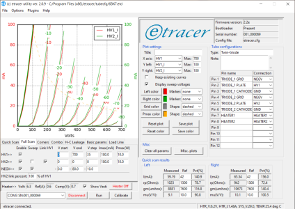
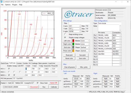
Check out these curves PB - I recently purchased a curve tracer. The first set are both triodes traced and overlaid on eachother. With a single triode resistively-loaded cathode follower, operating point would be around 330V, 15mA, -35Vg1.
Compare to the second set of curves, this is both triodes in parallel, operating point would be 330V, 30mA, -34Vg1. The linearity is much, much better!
So, think I will use the 3K resistor on the parallel cathodes of the two sections running at 15mA a piece, just have to spec my negative supply for it.
Attachments
Fancy.
Yes, the current owner is quite happy with it.
L0rdGwyn
New member
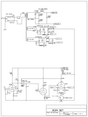
Here is my recent iteration PB, haven't prototyped this yet, but I feel pretty confident this is close to the final design.
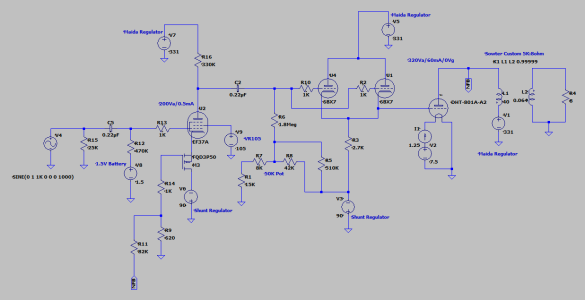
I dropped the CCS load on the pentode and the screen DC feedback. What I found was I was getting an H3 dominant THD spectrum and the sound suffered for it. Instead, what I am going to try is using a high-value resistive load with a VR105 glow tube regulating the screen at 105V. Inspired by some other DIYers, going to use 1.5V battery on the EF37A g1 and buffer the feedback loop with a PMOS on the EF37A cathode.
This gets a ton of sand out of the gain stage (less opportunity for oscillations), simplifies it significantly, gives me an H2 dominant THD spectrum and I believe the gain will be enough to get a good Zout. I think I've pushed the resistor load as well as the 6BX7 grid leak (max 2.2Meg) to their limits while maintaining a good operating point on the EF37A to maximize the gain.
I feel pretty good about this, I will pray to the oscillation gods before I prototype it and take some real-world measurements.
Attachments
Let us know how the breadboarding goes!
L0rdGwyn
New member
Got another random question for you PB, hope you don't mind.
Have you ever thought about loading a 6080/6AS7G cathode follower with an output transformer? Think a Bottlehead Crack with an OPT load. I recognize finding a transformer that is right for the job would be challenging as it would need to be gapped for 80-100mA at a low turns ratio, could do 1:1 but if you are going to the trouble, perhaps 2:1 or 4:1 to drop the output impedance. These are like, interstage and line output turns ratios, which typically don't come gapped for 100mA. Also would likely need to put a resistor between the primary and ground to bias up the cathode.
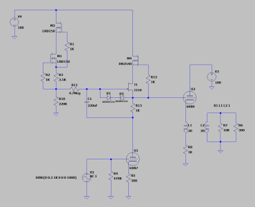
Something like this, gyrator loaded, direct coupled with an OPT load with a theoretical 1:1 OPT. Ever seen anything like that?
Have you ever thought about loading a 6080/6AS7G cathode follower with an output transformer? Think a Bottlehead Crack with an OPT load. I recognize finding a transformer that is right for the job would be challenging as it would need to be gapped for 80-100mA at a low turns ratio, could do 1:1 but if you are going to the trouble, perhaps 2:1 or 4:1 to drop the output impedance. These are like, interstage and line output turns ratios, which typically don't come gapped for 100mA. Also would likely need to put a resistor between the primary and ground to bias up the cathode.
Something like this, gyrator loaded, direct coupled with an OPT load with a theoretical 1:1 OPT. Ever seen anything like that?
Attachments
Are you talking about doing this for a headphone amp or for A2 drive?
I have thought about using a small push-pull output transformer in place of the center tapped choke to do an Altec 1570 variant, and possibly using the secondary as part of a feedback network of some sort.
I have thought about using a small push-pull output transformer in place of the center tapped choke to do an Altec 1570 variant, and possibly using the secondary as part of a feedback network of some sort.
L0rdGwyn
New member
Interesting amplifier, would love to see it. I was thinking more along the lines of a headphone amp. I have seen the idea discussed somewhat for speaker amplifiers, with a high-gain input tube, but obeying Vhk could become a problem at high outputs.
With the 6AS7 OTL headphone amplifiers like the Crack being so popular, I'm surprised I haven't found anyone trying this, but could be due to the oddball transformer that would be needed, probably a custom job. And who knows if it would really sound better than a simpler, cheaper output cap.
With the 6AS7 OTL headphone amplifiers like the Crack being so popular, I'm surprised I haven't found anyone trying this, but could be due to the oddball transformer that would be needed, probably a custom job. And who knows if it would really sound better than a simpler, cheaper output cap.
When you start your design assuming that you'll use an output transformer, you'd then really free up your choice of tubes to drive said output transformer, and there are many candidates that are far more linear than a 6080. Edcor makes some small 1.7K output transformers that would work for such an experiment.
If you aren't using an output transformer, then you want a tube with a good amount of transconductance that can also pass a pretty heavy amount of DC current.
If you aren't using an output transformer, then you want a tube with a good amount of transconductance that can also pass a pretty heavy amount of DC current.
L0rdGwyn
New member
Hey PB - going back to when you were using the 3C24, did you find an efficient way to degas them? I am attempting to trace their curves, have five different samples, all appear gassy and will not conduct on my pulse tracer.
I have read anything from running the filaments for five hours to running the plates red for 10-20 minutes since the tantalum plates are self-gettering, although for the latter I would concerned about arcing given the gas...
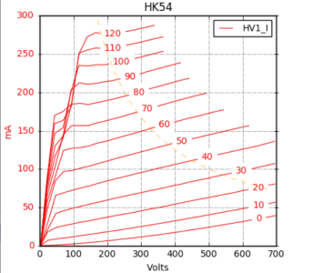
I have a pair of HK54 which I was able to trace A2 curves on no problem.
I have read anything from running the filaments for five hours to running the plates red for 10-20 minutes since the tantalum plates are self-gettering, although for the latter I would concerned about arcing given the gas...
I have a pair of HK54 which I was able to trace A2 curves on no problem.
Attachments
I degas them by throwing them away and using a different one when they are gassy. That's the big downside to the 3C24.
It's worth it to buy NOS in box with the 3C24. The ones with black plastic bases seem to be the best bet.
L0rdGwyn
New member
Sounds good, I was able to find a tested pair, black base like you suggested, thanks.
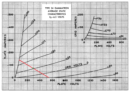
Can I ask your thoughts on a full A2 3C24 output vs. a partial A1 + A2? The below schematic seems to be the most popular design choice with the 0V grid being the positive swing boundary. Attached a 3.3K load line, wonder if it is worth adding a low voltage negative supply to get the additional 10-15V of negative grid swing? Thought about choke-loading the cathode follower for the negative swing, but might cause feedback issues.
Can I ask your thoughts on a full A2 3C24 output vs. a partial A1 + A2? The below schematic seems to be the most popular design choice with the 0V grid being the positive swing boundary. Attached a 3.3K load line, wonder if it is worth adding a low voltage negative supply to get the additional 10-15V of negative grid swing? Thought about choke-loading the cathode follower for the negative swing, but might cause feedback issues.
Attachments
L0rdGwyn
New member
Thanks for the schematic PB, choke loading the cathode follower with plate-to-plate local feedback, nice. What is the purpose of the 2.5V bipolar supply? I'll keep this in mind, think I would like to do something similar i.e. choke loading the cathode follower with local feedback and avoid a negative supply.