I took your pentode suggestion seriously PB, I have been doing lots of reading and I am working it up now.
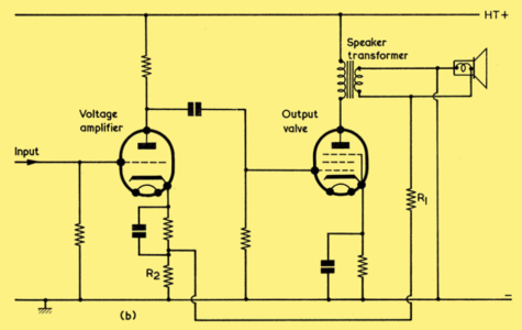
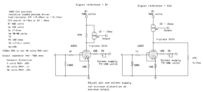
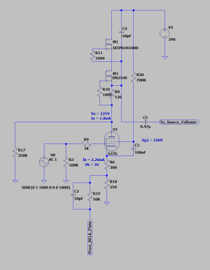
I was looking over some of the work Gary Pimm did on CCS loaded pentode stages. Looks like he came up with two different ways, the first with a high value resistor in parallel with the CCS, the other with the resistance to ground (picture attached). I am looking at using the EF37A or 6J7G on the input, I mocked up a model using plate to cathode feedback with Pimm's "resistance to ground" method. I need to take a closer look at the "paralell resistor" method, I am doing something wrong in LTSpice, since there is very little current across the resistor, there is no Vdrop and I am getting full B+ on the tube plate. I am sure the answer is obvious but my brain is getting tired.
In my sim with 250K to ground connected to the 6J7G plate, the open loop gain of the amp is roughly 59dB and the closed loop gain is roughly 44dB, so about 15dB of NFB. This leaves me with a mu of about 30 from the driver stage (open loop mu ~165), plenty of swing to drive the 801A to full output. With this setup, I would rewire my OPT to 6.5K:8ohm and a 370V / 50mA / -11 Vg bias point on the 801A.
I penciled in 50pF on the phase compensation cap, but will need to dial in the value. Overall I think this looks pretty good! I know it isn't accurate, but in LTSpice I am getting 0.25% THD at 1W, 0.56% THD at 3W. If that is anywhere close to real life results, that is an incredible improvement.
Will check my work a few more times and dial in part values, have some tubes on the way to give this a try.
") I plan to trick some tube purists at future meets, certainly no one would put a transistor in the signal path of an all DHT amplifier? Pure evil.
I plan to trick some tube purists at future meets, certainly no one would put a transistor in the signal path of an all DHT amplifier? Pure evil.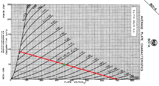
")