Wrong voltages, smoke, then nothing

Jclab

New member
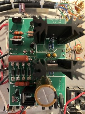
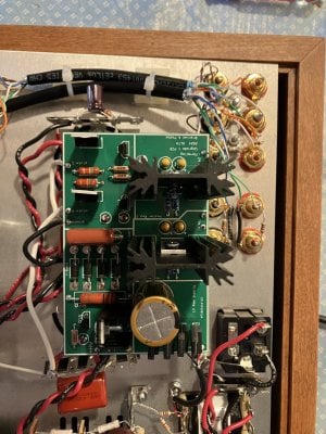
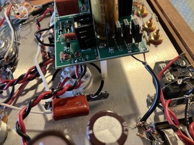
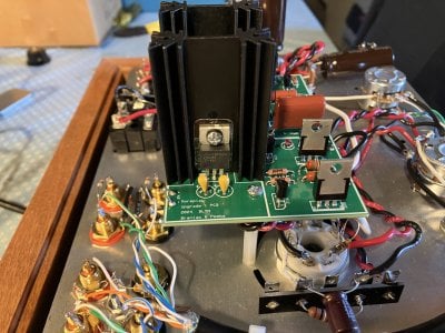
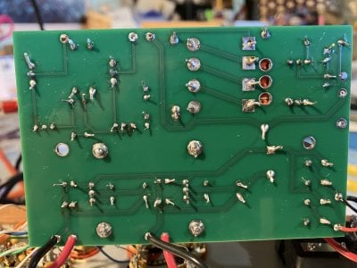
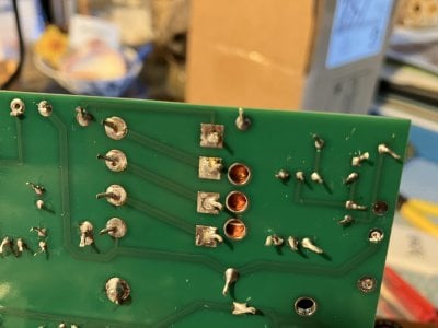
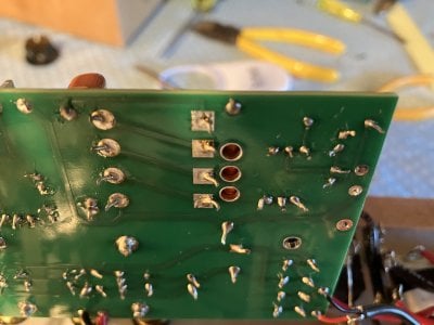
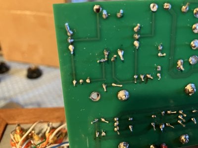
I just completed Assemblies 1 through 4. The low voltage circuit tested fine, 6.23 volts in each channel. When I tested the high voltage circuit, I got too low voltage on 6U and too high on 16U. B+ tested too high. As I was pondering those disappointing results, smoke started rising from the Zener zone area, though I could not tell from what component. I also noticed that LEDs D1B and D2B did not seem to be lit. I tried re-testing, but all testing points went to zero, though diodes D1A and D2A were still lit.
I was very happy with Moreplay before the upgrade, I guess the better is still the enemy of the good...
Thanks for any help ...
 
Here are some pictures:
 

Attachments

  • IMG_3148.jpeg
    IMG_3148.jpeg
    2.2 MB · Views: 29
  • IMG_3151.jpeg
    IMG_3151.jpeg
    2.5 MB · Views: 24
  • IMG_3152.jpeg
    IMG_3152.jpeg
    2.5 MB · Views: 21
  • IMG_3153.jpeg
    IMG_3153.jpeg
    1.8 MB · Views: 21
  • IMG_3154.jpeg
    IMG_3154.jpeg
    1.9 MB · Views: 20
  • IMG_3155.jpeg
    IMG_3155.jpeg
    2.6 MB · Views: 21
  • IMG_3156.jpeg
    IMG_3156.jpeg
    2.7 MB · Views: 22
I thought I had carefully examined the bottom of the board for solder bridges, but I guess I missed some... I'll try to take it apart tomorrow and send you a picture of the bottom. Thanks, Paul.
 
Thank you Paul, for being so quick. I just unwired my board though it was a bitch to wire in the first place. Here are some pictures of the underside. I cannot see any solder bridges, but those 78 years old eyes are not as keen as they used to…
 

Attachments

  • IMG_3157.jpeg
    IMG_3157.jpeg
    2.6 MB · Views: 19
  • IMG_3161.jpeg
    IMG_3161.jpeg
    2.2 MB · Views: 21
  • IMG_3162.jpeg
    IMG_3162.jpeg
    2.3 MB · Views: 20
  • IMG_3163.jpeg
    IMG_3163.jpeg
    2.2 MB · Views: 22
You'll want to get some side cutters to trim those leads back properly. I like the CHP-170, which are inexpsnive and do a good job.
CHP-170

The solder on your board looks a bit dull as well, what kind of solder is it? I'd also imagine cranking your iron temperature up a bit will help as well.
 
I just ordered a pair of side cutters. My solder is Sn 63 Pb 37 with 1.8% flux. My iron is at 800 °. What component do you think I fried and did you see any solder bridges?
 
Can you post a picture of the solder itself?

I don't see any solder bridges, which provides a little extra motivation to ask about the solder.
 
Here it is. I know, Chinese stuff, but I wired the original Moreplay from the same spool of solder with no problems.
 

Attachments

  • IMG_3164.jpeg
    IMG_3164.jpeg
    2.1 MB · Views: 19
Well it says rosin core on it, so that alleviates that concern.

I'd trim off the leads poking out on that board, then reheat all the joints to get them to flow out a bit more, though you can probably skip the LEDs.
Once that's done, throw it back in and take a quick DC voltage measurement at "reg TP".

-PB
 
My wife happened to have side cutters, so I retrimmed the leads. I also reflowed the joints. Can you tell me if the board looks ok before I reword it? I know, it looks dusty now, I’m going to wipe it first.
 

Attachments

  • IMG_3165.jpeg
    IMG_3165.jpeg
    2.5 MB · Views: 20
I meant “before I rewire it”. Also, do I need ti connect the black and white wires too before the reg TP measurement?
 
I rewired the board. Measured at reg TP. Nothing, -27 Mv , same as no contact with TP. LEDs D1A and D2A were lit but NOT D1B and D2B. Something must be open…
 
I would be suspicious of the middle leg of Q2A not being adequately soldered. What DC voltage do you have at the red wire entering the upgrade PC board HV+ pad?
 
I reflowed the 3 legs of QA2. No voltage at HV+. Also, it seems the filaments on the tubes were not lit.
 
Back
Top