What DC voltage do you have at terminal 21?
You are using an out of date browser. It may not display this or other websites correctly.
You should upgrade or use an alternative browser.
You should upgrade or use an alternative browser.
Wrong voltages, smoke, then nothing
- Thread starter Jclab
- Start date
How about 24 and 28?
I'd go back to the original manual and perform the power transformer AC voltage measurements found on page 29.
If these look good, then you have a loose connection in the power supply that is acting up.
If these look good, then you have a loose connection in the power supply that is acting up.
Power transformer measurements were within specs. That’s how I found out my meter was not working right. I used another (cheap) meter. I also remeasured reg TP, 21, 24 and 28. This resulted in a 1 all the way to the left of the display with no trailing zeros.
I also rechecked the wiring of the Power Supply with a flashlight, magnifying glass and wiggling the connections. I could not find any loose connections.
Sorry to be such a pain. I was very happy with the sound of the stock Moreplay. I originally only wanted to change to the Alps controls because of the 4db less insertion loss, but reading the comments of those who upgraded, I just had to try. Right now, I’m thinking of going back to the original circuit unless you have better ideas. Thank you very much for your help so far!
1 all the way to the left of the display means you aren't on the correct range.
400V at reg TP means there's a ground issue, so a black wire in the kit is loose or broken.
400V at reg TP means there's a ground issue, so a black wire in the kit is loose or broken.
They will show continuity with the teeny amount of current the meter uses to verify that, but there's at least one that's not super well connected. The easier way to deal with this is to reheat every solder joint in the kit where a black wire lands, excluding the heater wiring that goes to pins 2 and 7 on each tube socket.
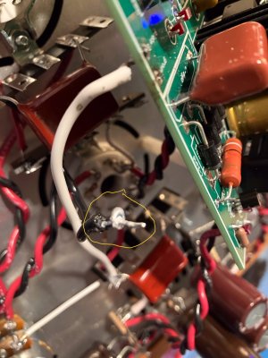
I think I’ve found the culprit. The soldering pad of the black ground wire came loose off the board. It must have as I was trying to put the wire back in. I had to ream the hole. Darn pc boards, I prefer point to point!
Now, what’s the best way of restoring the ground on the board?
Thank you again, I hate to waste your time!
Now, what’s the best way of restoring the ground on the board?
Thank you again, I hate to waste your time!
Attachments
If you put your soldering iron on what looks to be the pad, it may just melt away. Often solder will take that shape and look like the solder pad.
The boards are through hole plated and very resistant to this kind of thing happening.
The boards are through hole plated and very resistant to this kind of thing happening.
You were right, it was solder, not the soldering tab. I reheated all the black wire soldering points, replaced the black wire going from ground to 12U, the meter still reads 397 volts at reg TP. I tried putting the black meter lead on a black wire on the balance control, same 397 volts. I don’t know what else to try…
Yes, so the black wires on the balance control connect all the way back to the ground in the power supply. Yours are not connected. If the build was otherwise working properly prior to adding the upgrade, then this is a loose connection or a broken wire along the ground path somewhere. You can start back in the power supply at the last 220uF capacitor and measure DC voltage to the banded end of that cap, then follow the black wire that leaves there, and measure along the way. That will go into the upgrade board, then output of the upgrade board and into the amp. Follow the black wire around and measure DC voltages until you go from 0V to something else, then you'll find where this has been disrupted.I tried putting the black meter lead on a black wire on the balance control, same 397 volts. I don’t know what else to try…
23 is where DC ground originates. 24 is on the high voltage side of the power supply.
You need to measure the DC voltage at 23, 12, 2, the black wires at the balance pot, and the black wires of the volume pot. There are going to be a bunch of 0V values, then one that isn't.
Seeing -9.37V where you should have several hundred volts is just additional evidence that there's a loose connection in your Moreplay.
I just re-bolted the board on Moreplay and decided to take comprehensive measurements. Tubes are in, filaments are lit.
Transformer 9: 113 volts
Transformer 10: 113 volts
On the ground side: 31: -18 volts
32: 2 volts
26: -9 volts
23: -0
HV-: -0
Ground (on board): -0
12: -0
Balance pot: -0
Volume pot: -0
On the HV side:
28: 243 volts
24: 233 volts
21: 223 volts
HV+: 223 volts
Reg TP: 187 volts
6U: 121 volts
16U: 132 volts
4U: 8 volts
14U: 8 volts
In other words, it seems to be in specs now. If you think it’s ok, I’m going to try it before I rewire with the Alps controls. I’m now thinking that it must be the 23 to HV- connection which must be intermittent. Should I replace it before trying? Thanks again for your help, Paul!
Similar threads
- Replies
- 8
- Views
- 463
- Replies
- 13
- Views
- 5K
- Replies
- 7
- Views
- 2K
- Replies
- 10
- Views
- 24K