Speedball Upgrade Smoking!

Alright, the crack passed all resistance checks, so I plugged the tubes in and went about conducting voltage tests.

Here are the results for terminals 1-10:
1 - 72.5V
2 - 164V
3 - 0V
4 - 165V
5 -  157V <--- too high

6 - 0V
7 - 97V
8 - 0V
9 - 155V <--- too high
10 - 0V

Also do note that after testing the 12AU7 tube was warm but not hot to the touch. I could still very comfortably touch it whereas the 6080 tube was much hotter.

Any insights on what might be causing such high voltages at terminals 5 & 9? Thanks a bunch!
 
The center leg of the MJE350 feeding terminal 5 may not be adequately soldered.

If this is the Speedball 1.1, the instructions call for checking the voltage on the small board before proceeding with the rest of the upgrade.  Did your amp pass those checks?
 
I'm almost positive the small board passed those voltage checks, yes. Also, the center leg of the MJE350 looks pretty well-soldered to me (see photo attached).

I'll can try to rerun the Speedball 1.1 voltage checks, and get back to you.
 

Attachments

  • MJE_350_underside.jpg
    MJE_350_underside.jpg
    1.2 MB · Views: 35
After a very long hiatus (I really needed to focus on school for a while), I've decided to resume the repair process and finally get my Crack up and running again.

My Crack passed all resistance checks last year, but I wanted to test again before applying voltage, just to make sure nothing had loosened or corroded over time.

This time around, all terminals gave proper resistance readings EXCEPT for Terminal 6, which gave a reading of 2.48kΩ. Terminal 10 did read 0.5Ω, not exactly 0, but I think that's okay.

Note that there were no tubes installed and no aux adapter plugged in, and the power switch was set to off (not that I suspect it makes any difference). Also, please recall that I have the small Speedball board installed, but not the large Speedball board... instead I've reinstalled both 3kΩ resistors.

What do you suspect is the issue here?
Thank you for your time :)
Jordan
 
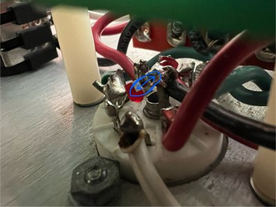
Hmmm, the 1/4" jack wiring looks pretty good to me (see photo attached).

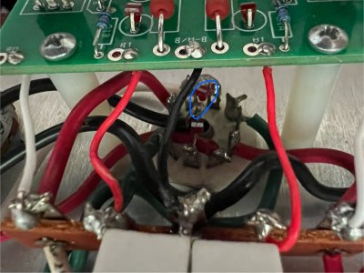
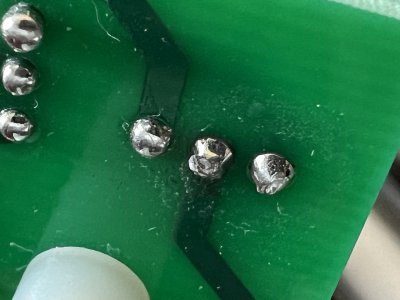
Interestingly, I did just notice that one of the LEDs on the bottom of the smaller tube socket has a severed lead (circled in blue in photos attached). It's the LED nearest the very bottom edge of the amp. Earlier in this thread, I was having problems with the smaller tube during voltage testing (please scroll up and see my post from June 1st). Could this LED be the issue?

Thanks
 

Attachments

  • severed-led.jpg
    severed-led.jpg
    536.2 KB · Views: 17
  • severed-led-angle-2.jpg
    severed-led-angle-2.jpg
    564.7 KB · Views: 12
  • headphone jack wiring.jpg
    headphone jack wiring.jpg
    1.7 MB · Views: 18
The outer lower and outer middle lugs on your headphone jack don't look like they have been adequately heated for the solder to flow out.

Yes, you'll need a new LED on the socket where that one is broken. 

 
Back
Top