mcandmar
New member
Babybottle 2.0
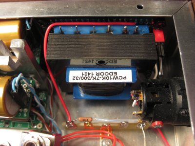
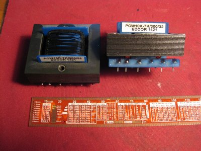
For a while i had been thinking about running the 3S4 tubes with a higher voltage to squeeze more power out of them, tricky part was working out what voltage i needed and how to achieve it. The tube datasheet lists a recommended maximum plate voltage of 90v, and a screen voltage of 67.5v, and the Speco output transformers are rated for 70v. With those limitations in mind the second challenge was to design a power supply close to those specs using as many of the original parts as possible. Preferably using the existing transformer with as little changes to the overall layout as possible.
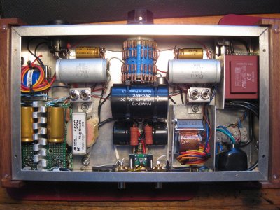
To recap: The main transformer has a dual secondary of 18v 400ma each, wired in series it was giving me ~43v AC no load, which after rectification and filtering with a CLCRC supply gave me a nice quite 45v B+ supply.
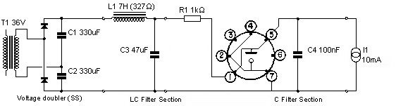
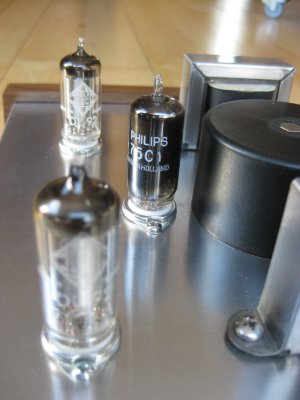
First experiment was to take the same transformer and feed it into a voltage doubler circuit which gave me ~115-120v. Unfortunately this was much higher than i needed, and no matter how i laid out the CRC and CLC filters i just couldn’t find an elegant way to shed the best part of 50volts without resorting to big resistors dumping it as heat. Then a light bulb lit over my head in the forum of a neon gas regulator tube. A quick search turned up the OC2 as a candidate which has two european variants the 75C1 and an STR75/60. The later two i just happened to have in a box (i might have bought a few box's of tubes on ebay). Looking at the specs they use the same 7pin miniature base as the 3S4, same glass size, 75v regulated output, 2-30ma current capability, and the best part is an ignition voltage of approx 115v. Talk about made for it!
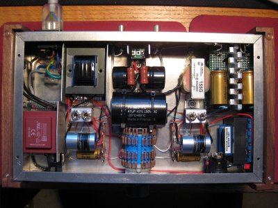
After a bit of experimentation with PSUD i mocked up a supply that worked rather well, noise level was perfectly acceptable with 2.7mv of ripple before the regular tube which gave me a nice quiet and regulated 75v B+ supply that i could feasibly package inside the enclosure. With the supply connected to the circuit i tried a few different operating points, with the regulator giving me a B+ of 77.5v i ended up settling for a 1.5k bias resistor which gave me approx 61v at the plates with ~4.5ma current. Total current draw measured 9.3ma for both tubes.
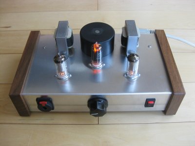
Final step was to go back to the forum and double check my findings with the ever helpful PJ to find he already had an operating point worked out that was surprisingly close (72v plate supply, 1400 ohm cathode resistor, ~4.25mA). Dont you love it when a plan comes together and everything just falls into place. The most difficult part of the entire project was having the courage to drill another 16mm hole in the chassis plate for the regulator tube. Once i mustered up the courage the actual build took less than an hour.
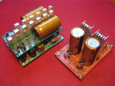
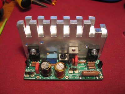
Following on from the filament transformer change in the previous post the slightly higher voltage had the 10v filter caps running at ~9v which was a little close for comfort. For reliability and peace of mind i upgraded them to 16v rated Nichicon FG's and fitted larger heatsinks onto the voltage regulators. I also took the opportunity to replace the Audio input wiring with some shielded silver plated teflon insulated wire while everything was apart.
Complete list of parts changed,
-x2 Cree CSD1060 diodes & x2 Elna 300uf 100v caps in a voltage doubler configuration
-x1 1k 5w resistor limiting current into the regulator tube
-x1 K40y .1uf 400v PIO capacitor to bypass the regulator
-x1 Philips 75C1 tube & 7-pin tube socket
-x2 Nichicon FG 10,000uf 16v
-x2 35mm TO-220 Heatsinks
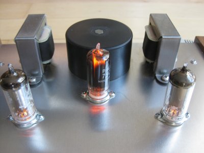
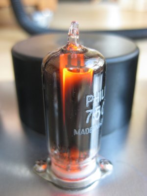
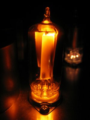
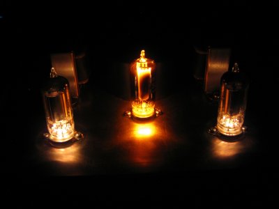
Conclusion, a wee bit more power, and strangely a better sounding amp too. I don’t really know why but it sounds less fluffy and more delicate than it did before. With the Grados its completely silent, and with both the Grados and HD650's it has more than enough power to drive them so i'm calling this a complete success. The 75C1 is an interesting little tube in that its glass is completely dark, but when running i just can’t help but sit and stare into it as it’s so warm and cozy looking")
For a while i had been thinking about running the 3S4 tubes with a higher voltage to squeeze more power out of them, tricky part was working out what voltage i needed and how to achieve it. The tube datasheet lists a recommended maximum plate voltage of 90v, and a screen voltage of 67.5v, and the Speco output transformers are rated for 70v. With those limitations in mind the second challenge was to design a power supply close to those specs using as many of the original parts as possible. Preferably using the existing transformer with as little changes to the overall layout as possible.
To recap: The main transformer has a dual secondary of 18v 400ma each, wired in series it was giving me ~43v AC no load, which after rectification and filtering with a CLCRC supply gave me a nice quite 45v B+ supply.
First experiment was to take the same transformer and feed it into a voltage doubler circuit which gave me ~115-120v. Unfortunately this was much higher than i needed, and no matter how i laid out the CRC and CLC filters i just couldn’t find an elegant way to shed the best part of 50volts without resorting to big resistors dumping it as heat. Then a light bulb lit over my head in the forum of a neon gas regulator tube. A quick search turned up the OC2 as a candidate which has two european variants the 75C1 and an STR75/60. The later two i just happened to have in a box (i might have bought a few box's of tubes on ebay). Looking at the specs they use the same 7pin miniature base as the 3S4, same glass size, 75v regulated output, 2-30ma current capability, and the best part is an ignition voltage of approx 115v. Talk about made for it!
After a bit of experimentation with PSUD i mocked up a supply that worked rather well, noise level was perfectly acceptable with 2.7mv of ripple before the regular tube which gave me a nice quiet and regulated 75v B+ supply that i could feasibly package inside the enclosure. With the supply connected to the circuit i tried a few different operating points, with the regulator giving me a B+ of 77.5v i ended up settling for a 1.5k bias resistor which gave me approx 61v at the plates with ~4.5ma current. Total current draw measured 9.3ma for both tubes.
Final step was to go back to the forum and double check my findings with the ever helpful PJ to find he already had an operating point worked out that was surprisingly close (72v plate supply, 1400 ohm cathode resistor, ~4.25mA). Dont you love it when a plan comes together and everything just falls into place. The most difficult part of the entire project was having the courage to drill another 16mm hole in the chassis plate for the regulator tube. Once i mustered up the courage the actual build took less than an hour.
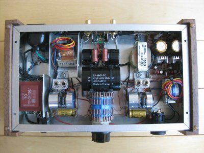
Following on from the filament transformer change in the previous post the slightly higher voltage had the 10v filter caps running at ~9v which was a little close for comfort. For reliability and peace of mind i upgraded them to 16v rated Nichicon FG's and fitted larger heatsinks onto the voltage regulators. I also took the opportunity to replace the Audio input wiring with some shielded silver plated teflon insulated wire while everything was apart.
Complete list of parts changed,
-x2 Cree CSD1060 diodes & x2 Elna 300uf 100v caps in a voltage doubler configuration
-x1 1k 5w resistor limiting current into the regulator tube
-x1 K40y .1uf 400v PIO capacitor to bypass the regulator
-x1 Philips 75C1 tube & 7-pin tube socket
-x2 Nichicon FG 10,000uf 16v
-x2 35mm TO-220 Heatsinks
Conclusion, a wee bit more power, and strangely a better sounding amp too. I don’t really know why but it sounds less fluffy and more delicate than it did before. With the Grados its completely silent, and with both the Grados and HD650's it has more than enough power to drive them so i'm calling this a complete success. The 75C1 is an interesting little tube in that its glass is completely dark, but when running i just can’t help but sit and stare into it as it’s so warm and cozy looking
")