Noise with Computers, USB DACs, and Powerline Ethernet Kits

So I pulled my last comment - I simply cannot replicate my static shock/energy jolt in the right channel of my headphone.

I tried Paul's suggestion of unplugging the inputs from my Crack with volume at zero; no static shock resulted.

I also tried to replicate with different tubes, on different days (even other days when static was present in the day) and could get no shock through the headphone, even though there would have otherwise been a static electric charge when I touched other parts of my equipment.

Must have been the tubes that was in place on the day.    :-(
 
Deke609 said:
For the purpose of this mod, you can think of a diode as erecting a barrier that is approx. 700 mV tall: @700 mV and below, no current flows, but everything above 700 mV passes over the barrier. (The "height" of the barrier, called the diode's "forward voltage" -- the minimum voltage required to turn the diode "on" and permit voltage and current to pass, varies a bit by type of diode). This applies to a "forward biased" diode - i.e., one where the anode is more positively charged than the cathode (banded end).  Because the mod uses two "reverse paralleled" diodes, there is a forward-biased diode in each direction: to earth ground and from earth ground -- so it blocks sub-700 mV currents in both directions.

In reality, the "barrier" is sloped and some small amount of current makes it through when the applied voltage is less than 700 mV.  See attached graph, and specifically the region to the right of the X,Y origin.

cheers, Derek


And there it is. An explanation simple enough for me to understand!. thanks PB for the brilliant Mod. and thanks to Derek for lifting the veil!
 
Hi, I am currently trying this mod on my Extended Foreplay 3. I am using 1N4004 diodes.
There is a drain wire from the power switch cable connecting the IEC power entry to the first ground lug and then it continues to the ground lug from the power transformer.
When I do the mod I am assuming I need to clip the drain wire between the IEC and the first ground lug but leave a connection between the first ground lug and the transformer ground lug. This is how it is done in the Crack.
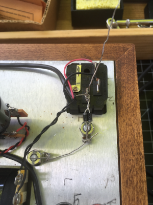
I am wondering if it would be better to route the drain wire from the power switch directly to the transformer ground lug and not to the IEC ground? The photo just shows my layout nothing soldered yet and no clipped leads yet. If somebody can confirm that I would appreciative it. Thanks, Best, Stefan
 

Attachments

  • IMG_9277.png
    IMG_9277.png
    538.6 KB · Views: 69
That works for noise control, but is not as safe as it should be. The chassis plate and transformer cores should be bonded to the safety ground with no interruptions; the ground lift should occur between the signal ground and chassis; i.e. at terminal 28.

That's a pretty inconvenient location, unfortunately - a great many wires go to that terminal. It will be tricky!
 
Thank you Paul, indeed terminal 28 would be tricky. PB said on the first page of this thread:

Paul Birkeland said:
I don't see issues doing this with any of our products.  I do also plan to test whether a UF4007 can throw a 20A breaker and survive, as this could also be a suitable part to use.

If you are saying that this mod is not the safest for the Foreplay then I would consider reversing it, it's nice without the noise but I rather would go the safe route.
Could you or PB confirm the safety of this mod? Thanks, Best, Stefan
 
This is a workaround for older kits.  For new kits, we separate the audio ground and the chassis plate with the antiphase diode arrangement plus some other parts, and this is the safest choice.  For our older kits that are not designed from the start to have these parts, the solutions are less than ideal. It would take a very catastrophic failure (like say replacing the power cord on your electric clothes dryer with the power cord plugged into the wall, then dropping the bare end of the power cord onto your Foreplay's chassis plate) to cause problems with the diodes installed, but it is remotely possible.
 
Hello,

Just finished my stock Crack build and I’ve discovered through process of elimination that my crack produced a static noise whenever my FIIO K5 Pro external DAC/amp’s USB is connected to my desktop computer. The static increases in volume when the volume on the crack is increased but not when the DAC/amp’s volume is increased.

I’m pretty confident that my solder joints are good, as tapping on the unit produces no distortion or anything audible.

I’m wondering if using an optical connection would resolve the issue.

I would greatly appreciate any advice or help anyone is able to offer regarding this issue.

Thanks I’m advance.

Tom
 
Aha!

I had read that thread as it sounded similar and wondered, but did not want to assume.

I think I will move forward with adding a ground breaker, thank you much!

Would you mind explaining why this is happening and how this fixes it? I found it interesting because whenever I moved my computer mouse I could cause a noise in addition to the background static.

Tom
 
The diodes create some separation between the Crack earth and the earth of the computer, which will interrupt the flow of low level noise that would otherwise be there. 
 
I want to try this on my SEX kit.  I also have USB noise on my odac.

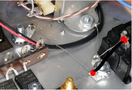
I drew a picture of what I think needs to be done.  So basically I solder the twisted diodes at the red points and the black line represents the twisted diodes. Anything I am missing?

Also currently looking at the 1n4007 for this mod.  Anyone have a better recommendation?  I guess the ones Paul mentioned are all good for this.

Does this look correct?
 

Attachments

  • sex kit mod.png
    sex kit mod.png
    1.9 MB · Views: 73
1N4007 will do the job.  The little piece of bus wire going from the solder lug on the chassis up to the IEC power entry module needs to be removed in the process as well, as the diodes are taking its place.
 
Thanks Paul, if I understand correctly just the single piece of bus wire going up to the IEC power entry module should be removed. 

The 2 other pieces of bus wire should remain, correct? 
Also should I reverse the polarity of the diodes like in your original picture?

Much appreciated.
 
Yes, the piece of bus wire wire going to the earth lug on the IEC power entry module is removed and replaced by the pair of diodes.  The diodes need to be wired antiphase.
 
Totally needed for me.  Also worked like a charm!!!

Like, static, that changes pitch depending on the screen.  Pulled the RCA, and dead quiet, so I knew the noise was after the Crack.  And now....holy flippin' motherlovin' cow!!!  It made my HD650s come to life!!!
 
Hi there,

I've been reading this thread (and others) and didn't find my situation covered.
My Crack + Speedball produces crackling/noise on the left channel. Only power and headphones are plugged in, nothing on the RCA jacks. Turning the volume pot doesn't affect this.
All joints seem fine, poking around and re-heating many didn't make a difference.
What I've observed: my laptop (and monitor etc) are sitting right beside the Crack.
a) unplugging the laptop (and all other devices in this room) from power doesn't affect the crackling
b) unplugging the laptop AND moving it 4-5meter away: the crackling stops

Could this be solved through the suggested diode mod as well?
 
Back
Top