EricS
Member
I see what you are saying about the power and output transformers, Paul - thank you.
I reread the section in Morgan Jone's book about transformer alignment and I think I was misunderstanding his intention. Most of the reference I came across online indicated aligning the transformer laminations at 90 degrees to one another and the more important part is the alignment of the coil winding axis (duh...).
I also found a helpful piece of advice on another forum that suggested laying out all of the parts as indented in the completed amplifier then energizing the power transformer. Then connect each transformer of interest to a DMM set to ACmV and see how much voltage is induced for each transformer at its intended location.
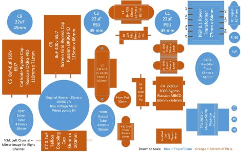
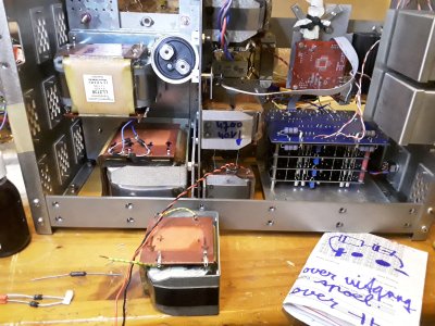
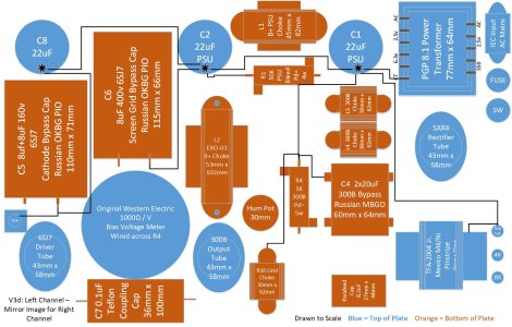
Doing this led to some minor adjustments. The output transformer seemed to be the most sensitive with 19mV being induced in the primary. Rotating it 90 degrees cured this, reducing the voltage down to 0mV. The B+ choke and the 300B filament chokes seemed rather immune to just about any placement relative to the PGP. I moved the EXO choke for the 300B plate back a little and repositioned the grid choke a little to reduce their interaction with the mains transformer as well. The resulting configuration is attached. I'm thinking this is as good as I can do right now until I prototype the layout.
This configuration works fairly well for a neat grounding scheme with a local star ground on each of the three big caps across the top of the diagram. I'll post a ground wire diagram shortly.
Please feel free to point out anything else that might look problematic at this point.
Thanks!
I reread the section in Morgan Jone's book about transformer alignment and I think I was misunderstanding his intention. Most of the reference I came across online indicated aligning the transformer laminations at 90 degrees to one another and the more important part is the alignment of the coil winding axis (duh...).
I also found a helpful piece of advice on another forum that suggested laying out all of the parts as indented in the completed amplifier then energizing the power transformer. Then connect each transformer of interest to a DMM set to ACmV and see how much voltage is induced for each transformer at its intended location.
Doing this led to some minor adjustments. The output transformer seemed to be the most sensitive with 19mV being induced in the primary. Rotating it 90 degrees cured this, reducing the voltage down to 0mV. The B+ choke and the 300B filament chokes seemed rather immune to just about any placement relative to the PGP. I moved the EXO choke for the 300B plate back a little and repositioned the grid choke a little to reduce their interaction with the mains transformer as well. The resulting configuration is attached. I'm thinking this is as good as I can do right now until I prototype the layout.
This configuration works fairly well for a neat grounding scheme with a local star ground on each of the three big caps across the top of the diagram. I'll post a ground wire diagram shortly.
Please feel free to point out anything else that might look problematic at this point.
Thanks!