Need Help with First Tube Build - WE91 300B Parafeed Derivative

Excellent!  Thanks to both of you!  Derek, I found that article last night shortly after I posted my question to the forum.  Should have known this is a topic Rod would have an article for...

I made a new round of measurements last night using my variac to reduce AC mains by 5-7v and see what happened with the rest of the circuit.  I think I'll need to wait until I have a transformer in hand to see how much actual voltage drop I get, then see if I need any new resistors to trim heater voltages.  I see the Hammond transformers are also specified with 117v primaries, so I it's not clear to me exactly what kind of voltage drop I'll get from a 6.3v secondary.  One step at a time...

Eric
 
I picked up two Hammond transformers, one is a 10vCT and the other is 12.8vCT.  My logic is that which ever one I didn't use would have utility in some other project.  The 10v one is better suited to my target voltage drop and as I expected, using half of the 10v winding gives a bit more than 5.0v drop. 

I wired both of them up and connected 200w worth of incandescent light bulbs (same draw as both amps) to measure the resulting voltages.  The 5.0v winding provides 6.8v worth of voltage drop with a 200w load on it.  My AC mains tend to range from 122v to 125v and the corresponding range after voltage drop is 115.2v to 118.2 which seems just about perfect of the primary of the PGP8.1 transformer.  I can get rid of the dropping resistors on the rectifier filament, but still need to trim the 300B filament by about one volt and take a pinch off of the input tube filament.  Need to wait for more resistors to arrive now... 

Almost there  8)
 
Finally had some time to return to this project after spending 5 weeks cleaning up the mess in my basement left behind by a washing machine that overflowed for 45 mins on the floor above  :'(  I've been through a few gallons of bleach lately killing the smell of mold and mildew, but it's almost back together again...  Now I have a $5 water alarm on the washer.

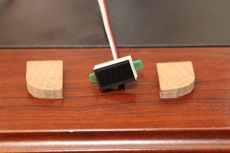
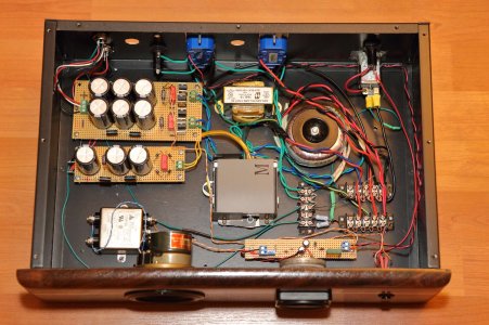
Anyhow, I finally wired up the the 10Vct transformer for my amps.  Got one amp adjusted last night.  I was able to completely remove the filament voltage dropping resistors from the rectifier.  I still need dropping resistors for the 300B and the 6SJ7 filaments, just smaller ones (which means they run a little cooler as well).  Here are some of the final voltage measurements at this point:

AC Mains:  124.6v
Mains after bucking transformer: 117.8vAC
Rectifier Filament:  5.04vAC (target 5.0v)
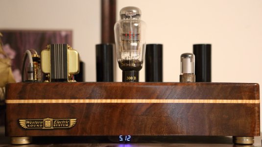
300B Filament:        5.12vDC (target 5.1v)
6SJ7 Filament:        6.4vAC    (target 6.3v)
B+ to ground before plate choke:  418v
B+ to ground at 300B plate:          398v
Voltage at wiper of humpot:            66.5vDC
300B plate voltage:          332v
300B plate dissipation:      22w

This looks better to me.  Haven't let it run for an extended time yet to measure temp reduction at the power transformer.  Will likely get there this weekend after I tweak the other amp.  I'm wondering if this might help tame some of the sub-400Hz noise I was seeing on the FFT of the speaker output - maybe the PGP was being pushed too close to the edge with 125v mains?

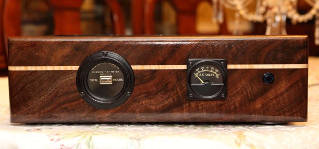
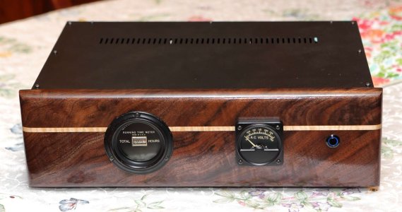
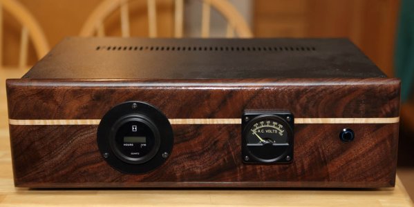
My plan is to build a nice box to house the bucking transformer.  I've also found a nice vintage meter with a 100v-130v scale and an old analog hours meter that I'll build into the face of the box.  A switch will energize two "lower voltage" outlets for the tube amps as well as a few more "normal voltage" outlets for my turn table, phono stage, and preamp.   
 
Thanks for the update! Those voltages look just about perfect.

And sorry to hear about the laundry disaster; what a mess that makes. Glad you were able to recover.
 
One amplifier has been modified to operate with the bucking transformer, the other has not.  Here are the final PGP8.1 temps after about 4 hours of use today:

With bucking transformer:      69c
Without bucking transformer:  72c

I just realized I neglected to measure ambient temp, oops.  Somehow I was expecting a larger temp difference.  I understand with solid state transistors, lowering the operating temp by 10c will generally lead to double the service life of the device.  Is there a similar rule-of-thumb for transformer longevity?
 
I have now modified both amps to run on something closer to 115-117vAC.  Temps are down a bit, the PGP8.1 power transformer runs a bit cooler at the top than it does at the bottom of the laminate stack.  I also noticed that the temp is hotter on the side the faces the rectifer tube by a few degrees.  After 4 hours of runtime, temps are closer to 65-66c (non-rectifier side), exhibiting a 44-45c rise over ambient. 

I ended up building a new box to power my analog rig: it has a single switch that controls two outlets on the back.  The first is standard household AC mains pass through, the second one uses the bucking transformer for a 115-1117vAC supply to the 300B mono amps.  This outlet has a separate 2A slow blow fuse to prevent overloading the Hammond filament transformer.  Inside the box are also my outboard power supplies for my turn table and my turn table preamp, both connected by an umbilical cord. 

I made a nice front panel to match the amps and installed a vintage voltmeter and a vintage hours meter.  I liked it very much until I plugged it and found that the mechanical hours meter makes a bit more whirling noise than I want.  I'm thinking I'll look for a more modern replacement that will run more quietly.
 

Attachments

  • IMG_0664.JPG
    IMG_0664.JPG
    289.7 KB · Views: 39
  • IMG_0665.JPG
    IMG_0665.JPG
    162.2 KB · Views: 15
  • IMG_0667.JPG
    IMG_0667.JPG
    162.8 KB · Views: 23
Someone suggested that I insert a resistor and see if that reduces the noise level. It did reduce the noise, just not enough to make me happy.  Any resistor greater than 10k results in the meter not moving at all - it just buzzed. Smaller resistors in the range of 1k to 7k actually allow the meter to move and certainly reduce the noise, but still not to a level that I find acceptable.

Bummer. I think I'll need to look into digital meters and find a way to mount one inside the housing for the mechanical meter since all of the digital ones have a smaller diameter face plate. 

Thanks for the links, Tubejack.
 
OK, I feel like I cheated by replacing a period hour meter with a new digital one, but it is much more quiet than the original one that I chose.  I think it's time to call this one done and move onto other projects  :D
 

Attachments

  • New Hour Meter.JPG
    New Hour Meter.JPG
    123.4 KB · Views: 53
When I first built this amp, I wired the output transformer for 8-Ohm output.  I am contemplating adding another output terminal and a DPDT switch to the top plate of the chassis so that I can switch back and forth between 4R and 8R speakers.  Is a 6A/125v switch sufficient for this function?  Is there a reason that I’m not considering why I should not implement a speaker output switch like this? 

This is the specific switch I was thinking of using:
https://www.onlinecomponents.com/en/gc-electronics/35072bu-11403409.html

Thanks for any input and Happy New Year!
 
That is super duper overkill.  You are talking about a place where there's roughly 8V RMS appearing with about 1A of current, and you're unlikely to throw the switch while using the amp, so contact current ratings are far less important than doing something like switching mains!
 
Gotcha.  The primary attributes that caught my attention are that it was black, so it would match my overall color scheme, and it would fit in a hole that already exists in my top plate. ;) Maybe I could mount a smaller switch under the hood…
 
As it turns out, my mains voltage varies way more than I though it did.  Jac at EML specifies a pretty tight voltage window for the 300B heater, so I ended up using two different bucking transformers and implementing a switch to move between them as needed. 

Using half of a 10VCT transformer drops about 9VAC from the AC mains and is ideal during the winter months when the AC grid stays pretty close to 125vAC.  During the summer air conditioning months, the grid droops quite a bit and the 10V bucking transformer drops too much voltage, taking the 300B filament below the 5.0vDC minimum.  Half of a 5VCT transformer drops about 5VAC from the AC mains and works great during the summer. 

To keep an eye on the filament voltage, I picked up an LED voltmeter from Amazon.  I like this one because it has a calibration pot on the back:  https://www.amazon.com/bayite-Voltmeter-Motorcycle-Polarity-Protection/dp/B00YALV0NG/ref=cm_cr_arp_d_product_top?ie=UTF8 

The display is a bit bright, so I put a strip of LED dimming tape across the display:  https://www.amazon.com/dp/B00CLVEQCO/

The tape tames the brightness and makes it much more subdued, but still easy to read.  Mounting the LED to the inside edge of the chassis bottom makes it practically invisible unless you squat down and view it from directly in front.  While I didn't do any output FFT measurements yet, I cannot hear any adverse effects such as hum or distortion as a result.  Now it's super simple to keep the filament voltage in the recommended 5.00v to 5.25v range.


Attachments

  • IMG_04510.JPG
    IMG_04510.JPG
    237.1 KB · Views: 9
  • IMG_04509.JPG
    IMG_04509.JPG
    293.2 KB · Views: 19
Back
Top