jagmeetbatth
New member
hello
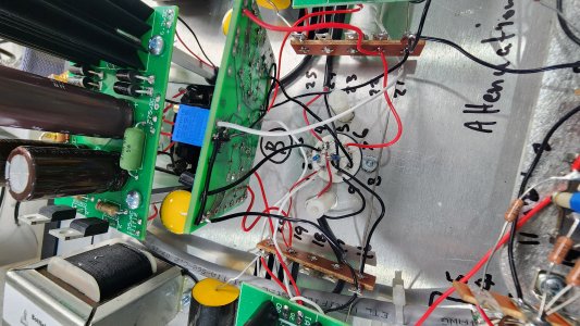
i am building amplifier using your kit and i am not getting leds on one of c4s board
the other board have leds light up
OB voltage with working c4s =around 220
OB voltage no leds c4s= 300 plus
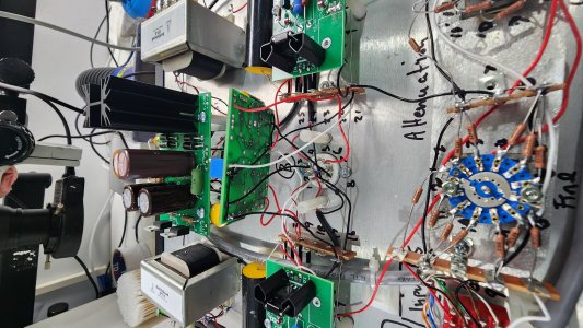
i am building amplifier using your kit and i am not getting leds on one of c4s board
the other board have leds light up
OB voltage with working c4s =around 220
OB voltage no leds c4s= 300 plus