missing leds on one c4s board

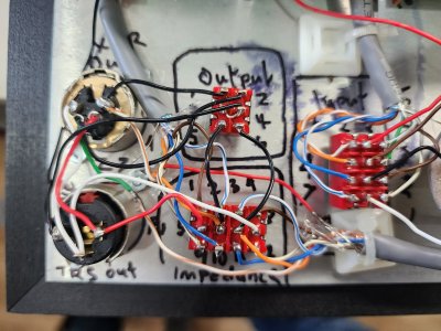
As best as I can tell, neither one of your 6C45P tubes is really drawing any current.  This can happen if they aren't receiving heater voltages (if they aren't lighting up), from poor solder joints (especially the center leg of the MJE5731A on the B side of the C4S board in this case), or possibly having the R1 resistors on the high current C4S boards swapped. 

The lower than expected Kreg voltages that you have tell us that the 12AU7 is tacking up the slack for the lack of current drawn by the 6C45P tubes, so it's unlikely that you have to be concerned with the A side of each high current C4S board, and likewise the outer portions of the center C4S board that hold the high voltage regulators seem to be operating happily. 

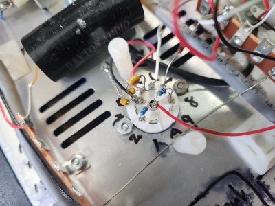
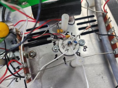
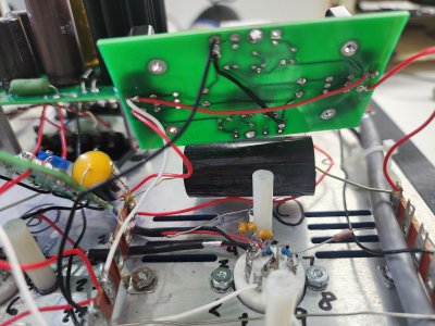
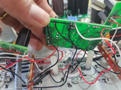
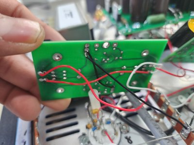
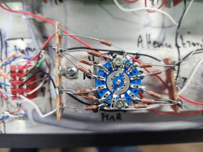
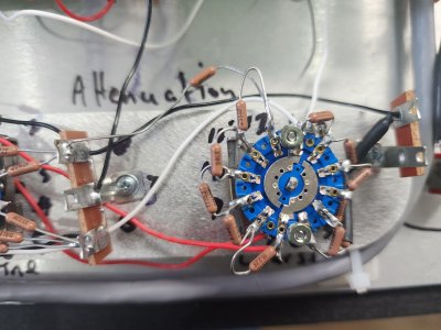
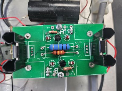
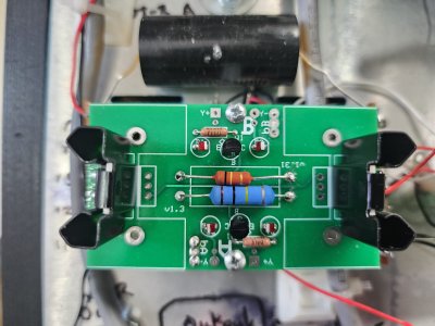
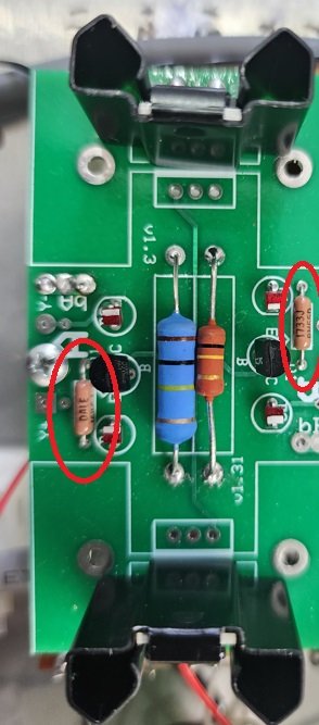
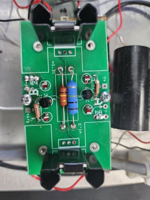
It is incredibly common for builders to make mistakes on that center PC board, especially forgetting to fold over the trim pot leads to make it into a variable resistor, but I don't see any obvious errors on yours. 
 
i can see both tubes lights up when turned on.
i checked potentio have folded legs also same as in diagram.
there are 4 small leds on each board ony two on A side lights up
on the b side no led lights up
 
i got lm431 replaced didnt make any difference i double checked all wirings and solder joints everything looks ok.all tubes get warm middle one hotter than other two.still no leds lighting on B side of small boards
 
Could I see both sides of the 6-7-8 terminal strip?

I'm also still very curious about the soldering products used, as it looks like some of the nuts in the kit are already corroding, which is a bit odd.
 
we are repair shop.
customer mentioned they have unfinished project from few years.we agreed to complete it for them.
rust is there maybe its old kit
we used same products we use to repair laptops.we do reball bga chips with this flux no issues so far
 

Attachments

  • 20231218_152155.jpg
    20231218_152155.jpg
    2.6 MB · Views: 6
  • 20231218_152036.jpg
    20231218_152036.jpg
    3.3 MB · Views: 0
  • 20231218_152041.jpg
    20231218_152041.jpg
    3.4 MB · Views: 0
  • 20231218_152043.jpg
    20231218_152043.jpg
    3.4 MB · Views: 0
  • 20231218_152056.jpg
    20231218_152056.jpg
    3.5 MB · Views: 1
  • 20231218_152103.jpg
    20231218_152103.jpg
    3.1 MB · Views: 0
  • 20231218_152108.jpg
    20231218_152108.jpg
    3.5 MB · Views: 2
  • 20231218_152150.jpg
    20231218_152150.jpg
    1.2 MB · Views: 5
some more
 

Attachments

  • 20231218_151923.jpg
    20231218_151923.jpg
    3.2 MB · Views: 0
  • 20231218_151926.jpg
    20231218_151926.jpg
    3.5 MB · Views: 1
  • 20231218_151931.jpg
    20231218_151931.jpg
    3.1 MB · Views: 1
  • 20231218_151935.jpg
    20231218_151935.jpg
    3.2 MB · Views: 2
more
 

Attachments

  • 20231218_151919.jpg
    20231218_151919.jpg
    3.2 MB · Views: 4
  • 20231218_151913.jpg
    20231218_151913.jpg
    3.1 MB · Views: 4
  • 20231218_151908.jpg
    20231218_151908.jpg
    3.2 MB · Views: 2
  • 20231218_151903.jpg
    20231218_151903.jpg
    3.1 MB · Views: 3
If the kit was really old before the HLMP-6000 diodes were installed, they are hygroscopic and can absorb enough moisture over time that damage can occur when soldering.  It may be worth a shot to replace the LEDs on the B side of each C4S board just to rule that out.  Also triple check that the R1 resistors on the high current C4S boards are the correct values.
 
with 12AU7  removed ob voltages stays 330v.

with 12AU7  installed i push power on OB on middle boards starts to rise from 3 to 5 volts and Ob on side two board starts to drop 330 to 245volts and stays at 245v
 
Here are some circled cold solder joints on one of the boards in the amp.  These kinds of soldering issues are a common cause for problems like this when building a kit.
 

Attachments

  • mainline C4S cold solder joints.jpg
    mainline C4S cold solder joints.jpg
    2.6 MB · Views: 23
i think they are well soldered i checked the continuity.because pads are running underneath it.
anythinng else othher than drysolder joints or bad solodering products.
 
As I mentioned before, the 6C45P tubes are refusing to draw current.  I posted some situations that could occur to cause that to happen.  Bad solder joints would be high on the list.  I would expect that some of those joints that I circled are so poorly flowed that the flux is residing between the through hole and the component lead.
 
Back
Top