Circuit Board Voltage issue [resolved]

Emoreigns

Member
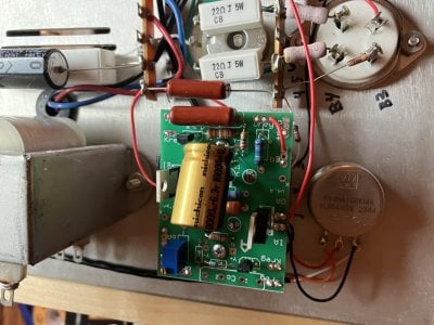
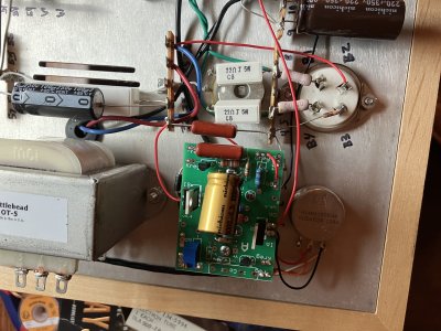
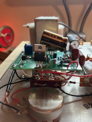
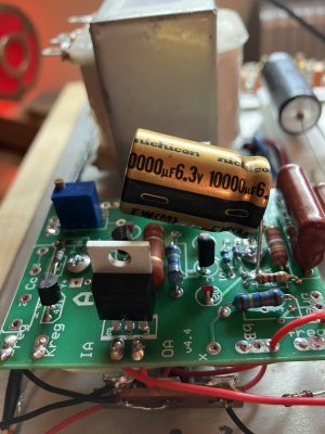
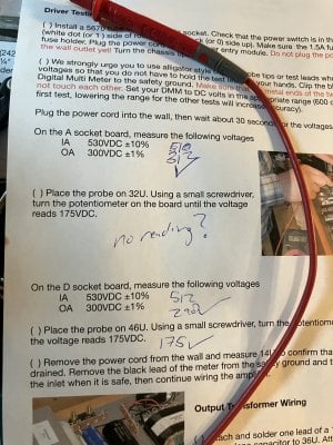
Doing the driver testing for the boards. The A socket, D socket, and 46U tested fine, but 32 had no reading whatsoever?

Trying to deduce if this is a problem on the board or elsewhere. Appreciate the help as always everyone.

IMG_6378.jpegIMG_6379.jpegIMG_6380.jpegIMG_6381.jpegIMG_6377.jpeg
 
Last edited by a moderator:
What does no reading mean though? Is it 0V?

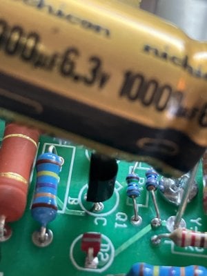
The simplest problem that will lead to super low voltage at that terminal is if you swap the R1 and the 33K resistor next to it on the B side of that board.
 
Yepp reading .001 V. Those two look the same as the other side of the board which is reading right?
 

Attachments

  • IMG_6385.jpeg
    IMG_6385.jpeg
    1.2 MB · Views: 27
The solder joints on those resistors haven't gotten enough heat to flow out.

To view this content we will need your consent to set third party cookies.
For more detailed information, see our cookies page.
 
I heated up all the joints and flowed some more solder. I'm still having the same reading. Might just be a skill issue lol.

The voltage readings on both of these resistors are the same as the 'correct' ones on the sister board, so it it seems like power is flowing?

Thanks Paul
 
Post some photos of the board. Close up and clear as you can.

Having just spent a week troubleshooting an issue that ultimately boiled down to me missing a joint that needed more heat, I can promise you it’s worth taking the time to go over those solder points slowly, methodically, and with a hot iron before doing anything else.

My biggest issue on PCBs normally ends up being spots without enough solder or transistors without enough heat.

 
Ok I went through took off the board and reflowed the joints. I connected and powered it, and am still having the same issue. I did notice that the 2 LED’s on the B side are not Turning on? Is that just indicative of the problem I already have or, did I just burn one of those out when soldering?
 
Paul you are a legend. R2B had one lead in the wrong hole. Thanks for the help as always. You are a legend Paul-

Have a good weekend!~ Hopefully get this build done this weekend!!!
 
Ok Paul/ community- I need some continued help. I got the build done on the Kaiju and got my speakers set up. Got inputs going in and speakers wired. Sounded great, so I added in the Beepree 2 which has been sitting complete for a while tested and unused. Beepree 2 got wired up and everything sounded even better. Got about 10 hours of listening in over a couple days, and I noticed the right channel was out. Upon inspection the right tube one the beepree 2 isn’t lighting anymore. Is this just a blown tube or something wrong with the amp? Seems like a blown tube, but the thing was brand new sans 10 hours of listening… Let me know I can take some measurements or send some photos. Appreciate the help as always everyone!
 
Did you swap the tube to see if it lights in the other channel? That will help show whether it’s the tube or another issue.
 
It is also extremely common for 2A3 and 300B tubes to be inserted into amps and preamps improperly, so if the non-glowing tube followed an instance of that tube being removed and put back in, that would be the place to start.
 
Tubes are properly inserted, big leads towards the rear. I don't believe I had moved these tubes at all during testing. Just powered and unpowered the Beepree 2 and Kaiju when I noticed the right channel was out and the lights on the right beepree 2 tube.

When I swap the tubes neither one will light on the right side, but both light up on the left which makes me think it isn't a tube issue right?

Thanks guys
 
What is the DC voltage between pins 1 and 4 on the offending socket? Typically, this is a bad solder joint on the green twisted pair of wires that feeds through the 0.51 dropping resistors to the 4 pin socket.
 
Both A1 & A4 are reading 0V- So, I should reflow these pins and the connections with the green wires @ 22 and 24 L?

Its strange these had passed voltage and lit up previously. I guess getting heated up for the first time might bring out some bad joints?

Thanks Paul,
 
Move back to where the two 0.51 ohm resistors land and check the DC voltage between those terminals. If it's still 0V, then move back to the + and - pads on the filament power supply board and check that.

Note that if you don't have the DC filament board, these measurements should be done in AC volts.
 
Back
Top