Do you have a little bypass cap on the screen? For the paralleled cathode followers, 1M seems like a reasonable grid leak choice.
You are using an out of date browser. It may not display this or other websites correctly.
You should upgrade or use an alternative browser.
You should upgrade or use an alternative browser.
CCS Loaded Parafeed Output - Design Considerations?
- Thread starter L0rdGwyn
- Start date
L0rdGwyn
New member
Yeah I thought 1Meg was a good choice, I will leave it as is. At the moment I do not have a bypass cap on the screen, I have seen it done both ways, got the idea from one of Pete Millett's amplifiers who left it unbypassed. I tried it bypassed with 0.1uF and without, but did not see a measurable difference in gain, distortion, FR, etc.
L0rdGwyn
New member
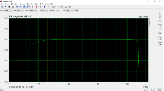
Thermioniclife said:Those test sockets are sweet. Nice flat frequency response !
And thanks, Thermioniclife! Sorry didn't see your comment until just now. The sockets are very nifty, sort of make the whole thing work. I have some noval 9-pin boards as well that can be swapped in if the design calls for it, will use adapters for any oddball tube bases if need be.
") ...John
...JohnL0rdGwyn
New member
HA! That has to be it, no doubt.
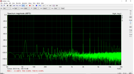
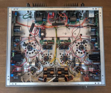
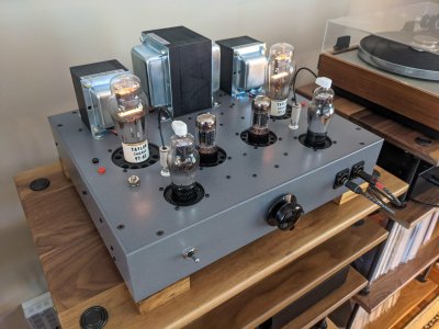
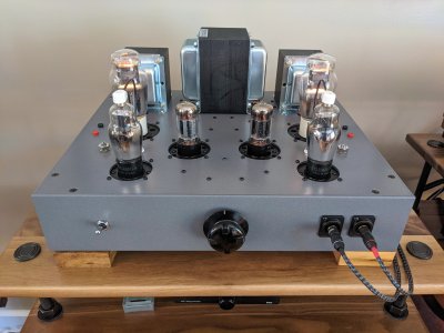
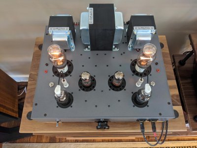
I finished the second channel, the heater regulator I was also using as a bias supply was injectin HF noise into the EF37A grid, so I had to make a switch, nice and quiet now. Maybe it was the tube swap, but the feedback and measurements improved in the final circuit, but HF extension, lower distortion and output impedance.
Output Z: 1.53ohm
Power: 6.2W into 8ohm
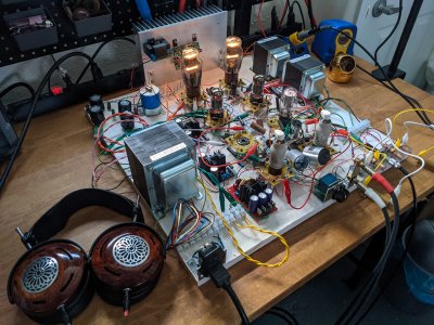
I had a listen with headphones, then lugged it into my stereo, the sound is very nice, will do some more tinkering of course but it won't be long before it is boxed.
I finished the second channel, the heater regulator I was also using as a bias supply was injectin HF noise into the EF37A grid, so I had to make a switch, nice and quiet now. Maybe it was the tube swap, but the feedback and measurements improved in the final circuit, but HF extension, lower distortion and output impedance.
Output Z: 1.53ohm
Power: 6.2W into 8ohm
I had a listen with headphones, then lugged it into my stereo, the sound is very nice, will do some more tinkering of course but it won't be long before it is boxed.
Attachments
There are lots of 100-ish watt transmitting triodes, now you can go for 40W!
 not sure when it will come to fruition, but have a nice protoboard to mess around with it now.
L0rdGwyn said:My next victim is thehk54HK254
The EL34 isn't a bad choice. Maximum cathode current is plenty high and high voltage isn't particularly bothersome.
L0rdGwyn
New member
I thought so too, took some measurements at a potential operating point, I found gm and linearity were better in the EL34 than say, parallel 6BX7 at high voltage, 440V B+. Shouldn't have a problem with the 60mA grid current at peak swing, I have a pair of NOS EL34 burning a hole in my pocket too.
With a similar feedback circuit to the 801A design, the challenge is the gain. For a 3K load to get 15W output with a 3:1 damping ratio with the HK54, will need something like 25dB of feedback. I grabbed a couple of high-gain pentodes to try out, 6EW6 and 6AH6, the 6EW6 being the higher of the two. With a 5-pack of NOS 6EW6, what I found was a high degree of variation in gm / the curves from sample to sample, even from the same exact batch, BUT they can be made to be matched pretty well by adjusting the screen voltage, so I would need an adjustable screen supply to match the feedback in both channels.
So we'll see, it's going to take some trial and error.
Looks great! How does it sound?
L0rdGwyn
New member
Really good, best of the amplifiers I have made so far, the real standout is the bass, unlocks a new level of potential from my Snells! Great clarity and detail too, the speakers disappear.
Thanks for your $0.02 along the way. First got the idea for an 801A build over a year ago now, figuring out how to make it happen was a serious learning experience.
Thanks for your $0.02 along the way. First got the idea for an 801A build over a year ago now, figuring out how to make it happen was a serious learning experience.