That was there as an experiment for tweaking the cathode follower bias to dial in the plate current perfectly. I didn't end up liking it so the power supply it there but that's no longer reflected in the schematic.
You are using an out of date browser. It may not display this or other websites correctly.
You should upgrade or use an alternative browser.
You should upgrade or use an alternative browser.
CCS Loaded Parafeed Output - Design Considerations?
- Thread starter L0rdGwyn
- Start date
L0rdGwyn
New member
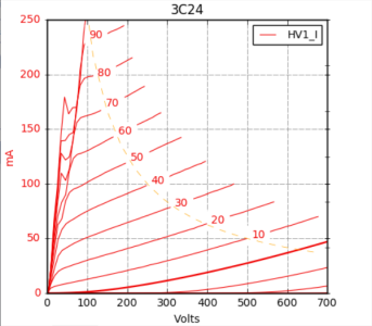
I got my functioning 3C24 PB. Traced the curves too, all looks well. Plate resistance around the bias point I am thinking is around 9.4K.
I might breadboard this with an E80F and 6AH4 with a negative supply, could be low voltage since the 3C24 grid only needs to swing down to around -25V. I have a spare Lundahl mains transformer, would only need one of the four 6.3V 3.1A windings, was thinking I would place the other three in series and use a voltage doubler for the negative supply, should get me something like -50VDC.
Did you really leave the EF86 cathode degenerated in your design, still had enough gain?
Also, just wanted to say, I know I am talking about my own designs on this thread (which might be renamed to "L0rdGwyn Pesters PB"), but I am a super BH ambassador, probably responsible for 10-15 BHC sales") people often ask me how to get into tube DIY. I tell them to read Valve Amplifiers and build a BHC. Excited about the YouTube channel announcement, will follow along.
people often ask me how to get into tube DIY. I tell them to read Valve Amplifiers and build a BHC. Excited about the YouTube channel announcement, will follow along.
I might breadboard this with an E80F and 6AH4 with a negative supply, could be low voltage since the 3C24 grid only needs to swing down to around -25V. I have a spare Lundahl mains transformer, would only need one of the four 6.3V 3.1A windings, was thinking I would place the other three in series and use a voltage doubler for the negative supply, should get me something like -50VDC.
Did you really leave the EF86 cathode degenerated in your design, still had enough gain?
Also, just wanted to say, I know I am talking about my own designs on this thread (which might be renamed to "L0rdGwyn Pesters PB"), but I am a super BH ambassador, probably responsible for 10-15 BHC sales
people often ask me how to get into tube DIY. I tell them to read Valve Amplifiers and build a BHC. Excited about the YouTube channel announcement, will follow along.Attachments
What you're messing around with is something PJ and I have been working with for a while, and to be completely honest there was a good 6 month period where it was me pestering PJ and seriously trying his patience, so this thread feels rather appropriate.
One thing PJ told me was that the unbypassed cathode resistor on the first stage pentode would improve performance of the amp. While this is absolutely true, I eventually made a really gnarly spreadsheet on the computer (that started out as a pentode operating point performance predictor from PJ) and this was able to show what bypassed vs. unbypassed cathode resistors looked like. The performance differences between the two were small enough that I don't worry as much about squeezing out that aspect as much as I did before.
One thing PJ told me was that the unbypassed cathode resistor on the first stage pentode would improve performance of the amp. While this is absolutely true, I eventually made a really gnarly spreadsheet on the computer (that started out as a pentode operating point performance predictor from PJ) and this was able to show what bypassed vs. unbypassed cathode resistors looked like. The performance differences between the two were small enough that I don't worry as much about squeezing out that aspect as much as I did before.
Paul Joppa
Moderator
The unbypassed driver cathode resistor does not provide very much feedback - around 6dB or so, I think.
L0rdGwyn
New member
Well I do appreciate the feedback (no pun intended), thanks gentlemen. In one of my 801A A2 prototypes, I left the cathode of an EF37A unbypassed, which significantly improved the sound, however the internal feedback was too much and I did not have enough gain remaining for the loop, at least in that particular iteration. In a DIY thread PB linked, which I am now following quite closely, a user implemented a PMOS transistor on the cathode in output plate to input cathode local feedback, buffering the feedback loop with very impressive results. This is what I am in the process of trying, using a resistive load. If it works out, might make it in a 3C24 prototype as well 
I've also split the cathode resistor into two resistors in series and bypassed one of them to split the difference a bit.
L0rdGwyn
New member
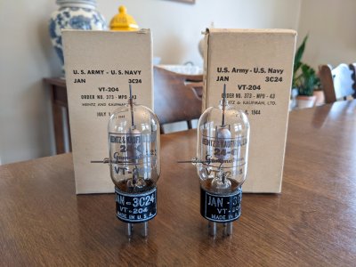
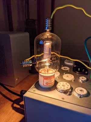
Here is my latest A2 transmitter craziness PB. A few months back when I was thinking about the 3C24, I picked up a pair of HK54. Price was $65 for a NIB pair, good deal in retrospect, was just curious but didn't know if I'd ever use them. Well now more serious about the idea as I am learning more about this topology, might even try them out in place of the 3C24 if I can find more pairs.
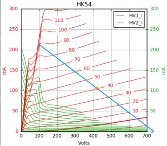
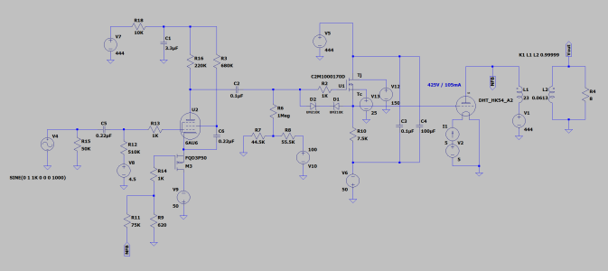
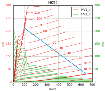
I traced A1+A2 and grid current curves on my tracer, came up with a 425V 105mA bias point using a 3K load, plate resistance is about 9K. I put together an LTSpice DHT model using Dmitry Nizh's modeling tool and made a simulation. Using 6AU6 on the input, get an open loop gain of around 220 from the stage. Given that the HK54 will draw a whopping 50-60mA of grid current at peak swing, thought a cathode follower was probably impractical (bias + grid current would make for a monster power supply), so a FET buffer instead. The gate would be biased positive using a voltage divider from the regulated B+, then a bias pot to dial in the HK54. For the output transformer, I subbed in the Lundahl LL1623 120mA model, 23H 164DCR primary, rated for 25W at 30Hz.
With this setup, I can apply about 22dB of feedback and get a damping factor of about 3.5:1, could improve that by changing the pentode to something like the 6EW6. This makes for close to a 15W amplifier, not bad for a 450V B+.
Attachments
60mA isn't impractical for a cathode follower. Try high gm tubes like the 6BX7, 6BL7, 6080, 6AS7, 5998, 12GN7, etc. With your 40V of bias, what's the standing grid current?
What I really like about what you've cooked up there is there's very little swing above the 0V grid voltage line, so that could make for a far simpler design overall without sacrificing much.
What I really like about what you've cooked up there is there's very little swing above the 0V grid voltage line, so that could make for a far simpler design overall without sacrificing much.
L0rdGwyn
New member
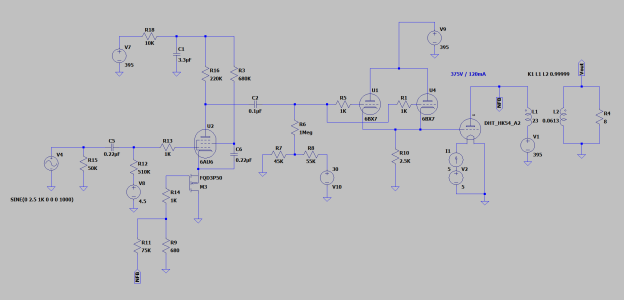
I thought the exact same thing on the negative grid swing, sacrifice a little power for a more simple power supply. I mocked it up both ways with that in mind. With the negative grid boundary being 0V, I rebiased to 375V 120mA. This brings the quiescent grid voltage to around 48V.
At idle, the grid will draw about 8mA. When I was mocking it with a cathode follower, I was looking at using the 6AH4, but might be better to go with 6BX7 or 6BL7 and parallel the sections, like I am doing in my 801A amplifier, which draws far less grid current. At one point I had thought to use the EC360, similar to a 6AS7G but single triode, but with the bias current + peak grid current, the B+ supply would be drawing something like 500mA. Going with a 6AH4 / 6BX7 / 6BL7, etc., the current draw would be much more manageable. As it so happens, I have quite a few 6BX7 and 6BL7 handy.
Put together a schematic below, still makes for a 10.5W amplifier without a negative supply and avoiding the A1/A2 transition point, the curves get much more cramped beyond. Would either need to run the B+ supply through a voltage divider or make a separate low voltage supply to bias up the CF grid. With each section of the 6BX7 biased at 10mA, idle current draw on the B+ supply would be around 300mA, then around 400mA at peak grid swing.
Another advantage of this approach - voltage swing around the 375V bias point is more linear, should make for a good first watt.
Attachments
I have a pretty strong proclivity toward amps that look like that design.
You could split the 2.5K cathode load into a Hammond 154E and a resistor in series as an experiment.
You could split the 2.5K cathode load into a Hammond 154E and a resistor in series as an experiment.
L0rdGwyn
New member
Ahh yes, something to try in breadboard, will keep that in mind. Could potentially get the full negative swing after all, so long as it doesn't anger the feedback gods.
Well I'm excited about this, altogether not an overly complex design without the negative supply. Need to decide if I want to change to a higher gain pentode for more than 22dB of feedback for a better damping ratio. Might try different amounts of feedback and tune by ear. The 3K 120mA 23H Lundahl is probably the best off-the-shelf transformer for the job, but will see if there are others out there.
Well I'm excited about this, altogether not an overly complex design without the negative supply. Need to decide if I want to change to a higher gain pentode for more than 22dB of feedback for a better damping ratio. Might try different amounts of feedback and tune by ear. The 3K 120mA 23H Lundahl is probably the best off-the-shelf transformer for the job, but will see if there are others out there.
I haven't found a single cathode choke in the feedback loop to be a problem so far. Our old Seductor amp used plate to plate local feedback and we did run into some instability depending on the value of the cathode bypass cap at the output, which was a bit of a surprise.
A damping factor of 3.5 will allow the amp to work in place of something like a 300B/2A3 amp without the bass character changing so much.
The One-Electron UBT-3 is a decent transformer for not a ton of money, but the maximum recommend primary current is 110mA.
The PRC-1 and our Kaiju OT's could be used in parallel feed well in that circuit as well.
L0rdGwyn
New member
That's good to know, gives me a lot of confidence using the choke then, would be great to get the 15W without a negative supply, I'll give it a shot. Thanks for the recommendations, let me think it over the transformer situation, think this would be next in the DIY queue after the 801A amp, which is probably two months or so from completion.
L0rdGwyn
New member
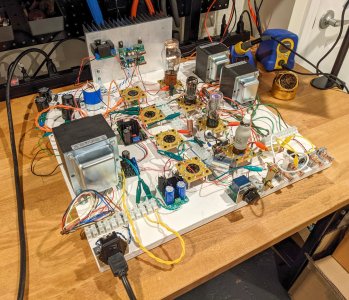
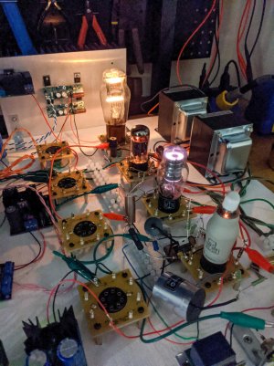
Hey PB - at long last, I have some preliminary results on my 801A A2 build. Since the circuit was going to need a breadboard anyway, I decided to put together a reusable prototyping board, I combined the two projects into one.
I finished the board a few days ago and finished a single channel of the amplifier. The plate-to-cathode feedback is buffered by a PMOS on the cathode of the EF37A. I had some heater regulators from another project on hand, so I put DC on the EF37A heaters then ran one end through a bias pot to apply grid bias to the pentode and dial in the operating point. I used a VR105 glow tube to regulate the EF37A screen.
In this first iteration, this comes out to around 11dB of feedback. Output Z is 1.7ohm, which is great, hit one target on the first go around. Clipping starts beyond 6.3W into 8ohms.
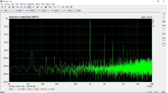
THD is a bit higher than expected, 1W into 8ohm spectrum below, which I attribute to the open-loop gain of the EF37A being much lower than simulated (I had thought I would be able to apply around 15dB of feedback), so that is what I will be investigating next. The harmonic spectrum is favorable, so even as is I feel confident the sound will be pleasing. Ultra low distortion wasn't necessarily a very high priority, we'll see how it sounds once I finish the other channel.
Edit: I should note that going from 1W to 6W, the distortion *only* climbs to 2.5%.
I finished the board a few days ago and finished a single channel of the amplifier. The plate-to-cathode feedback is buffered by a PMOS on the cathode of the EF37A. I had some heater regulators from another project on hand, so I put DC on the EF37A heaters then ran one end through a bias pot to apply grid bias to the pentode and dial in the operating point. I used a VR105 glow tube to regulate the EF37A screen.
In this first iteration, this comes out to around 11dB of feedback. Output Z is 1.7ohm, which is great, hit one target on the first go around. Clipping starts beyond 6.3W into 8ohms.
THD is a bit higher than expected, 1W into 8ohm spectrum below, which I attribute to the open-loop gain of the EF37A being much lower than simulated (I had thought I would be able to apply around 15dB of feedback), so that is what I will be investigating next. The harmonic spectrum is favorable, so even as is I feel confident the sound will be pleasing. Ultra low distortion wasn't necessarily a very high priority, we'll see how it sounds once I finish the other channel.
Edit: I should note that going from 1W to 6W, the distortion *only* climbs to 2.5%.
Attachments
mcandmar
New member
I've never heard of the 801a's before, you have very much peaked my interest as i use early 01a's in my preamp which are also tungsten thoriated DHT's, and fed with Coleman regulators. Any chance of sharing your design?
P.S. That is one of the cleanest proto boards i have ever seen")
P.S. That is one of the cleanest proto boards i have ever seen
L0rdGwyn
New member
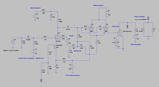
Thanks, mcandmar, don't mind sharing the design, but I have to warn that it is a bit of a doozy, complicated, at least by my standards. Both the output transformers and mains transformer are custom jobs, although you could probably make it work with off-the-shelf stuff, but likely more transformers needed, especially for the 801A filaments, I was able to get everything wound on a single core with internal shielding. The 801A is a tricky tube to use given its high plate resistance, necessitating either a high impedance OPT or use of NFB, I went with the latter after getting subpar results with the former. I've attached a pretty accurate amplifier schematic below.
Attachments
I like it!
L0rdGwyn
New member
Thanks, PB. Here's a technical question maybe you can help me out with: as I said I'm not quite getting the gain I expected in the pentode stage, I'd like to squeeze out a little bit more and apply more feedback. One way to do that would be to increase the grid resistor for the 6BX7. For autobias, the data sheet lists 2Meg max, I have a little less than 1Meg in my design since it is using sort of a mixed bias.
Think I can push that to 2Meg?
Think I can push that to 2Meg?
Thermioniclife
Member
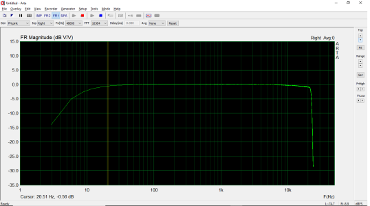
Those test sockets are sweet. Nice flat frequency response !