Yeah, do post your results, it's a useful reference.
You are using an out of date browser. It may not display this or other websites correctly.
You should upgrade or use an alternative browser.
You should upgrade or use an alternative browser.
CCS Loaded Parafeed Output - Design Considerations?
- Thread starter L0rdGwyn
- Start date
L0rdGwyn
New member
Okay PB, I have been quite the busy bee...here is where we are at with the parafeed caps in this amp, which is otherwise complete ")
I took FR sweeps of five different capacitances: 3.3uF, 4.7uF, 6.8uF, 8.2uF, and 10uF. Not sure how to insert attachments on the BH forum, but I have included them in a GIF format attached below, easier to see the relative change of low end response this way, but let me know if you would like the individual plots.
As you can see the effect on low end response from 20-30Hz is pretty subtle, we are talking about a difference of ~0.3dB when tripling the capacitance from 3.3uF to 10uF.
*I am copy/pasting/reformatting from another forum, subjective impressions were done in two different sittings.
Part 1:
Okay, so we've established there is a very small difference in frequency response from 20-30Hz. But how does the sound change subjectively? I first decided to compare at the extremes, 3.3uF and 10uF. The results were somewhat unexpected...
I much preferred the sound of the 3.3uF. Even if the low-frequency extension is marginally improved with the 10uF caps in, there is a very noticeable loss of soundstage, airiness, and detail. The treble sounds a bit more harsh to my ears as well with 10uF. The 3.3uF sound is much more spacious and cohesive. Up to this point I had mostly been listening with the higher capacitance caps (6.8uF and 10uF), but the sound is much improved with 3.3uF. In fact, the bass sounds better! Better definition even if the extension is objectively slightly worse.
So there are clearly two competing factors in play here that will need to be balanced when assessing the other three caps. I can say without a doubt I will not be using the 10uF, bigger does not necessarily appear to be better.
This is an interesting finding since using a lower value cap opens up many more possibilities in terms of the quality of caps that can be used. I had somewhat assumed I would need a value higher than 5.6uF, so my top choice was the Rike Audio S-Cap 2 (aluminum foil paper in oil) as these caps are the appropriate size, value, and are well-reviewed for their "neutral" sound. They are also quite affordable.
So, there is more listening to be done.
Part 2 (after the suggestion was made that differences heard between 3.3uF and 10uF may not have been all due to the capacitance - try the caps in parallel for lower ESR/ESL):
Worked on getting the parafeed capacitance nailed down this morning. I started by comparing the 4.7uF and 3.3uF in parallel vs. the single 8.2uF cap. I can say without a doubt the two parallel caps sounded better. Better sounstage, air, and detail. Similar to what I said about the 3.3uF vs. 10uF, the singular higher capacitance cap causing something of a collapse of soundstage and more harsh treble.
Next, I compared the 4.7uF cap to the 4.7uF and 3.3uF in parallel to compare a singular lower capacitance cap with the higher capacitance combination. Again, I felt the two parallel caps gave better detail, soundstage separation, and this is the first time I felt the bass was significantly improved between two sets of caps. Fuller, tighter, more body.
Next, I compared two sets of parallel caps with different capacitances. With what I had on hand, I went for the two lowest capacitance combos for the sake of practicality, 4.7uF + 3.3uF and 6.8uF + 3.3uF. This is where differences started to get more difficult to detect...however, I did feel vocals started to get smeared a bit with the higher capacitance and focusing on other aspects of my test tracks revealed a loss of microdetail.
So, with the parallel combination of around 8uF, I was getting the best sound. But what about the relative values of the two capacitors? I then compared the 4.7uF + 3.3uF combination with an 8.2uF + 0.22uF combination. Not an exact capacitive match, but close enough with the 5% tolerances. I felt the two caps of similar size gave better nuance and vocal detail.
If two paralleled caps is good, is three better? I put the 0.22uF cap in parallel with the 4.7uF and 3.3uF for a total of 8.22uF. Adding this 0.22uF cap undeniably reduced the fullness and quality of the bass.
So my winning combination was the 4.7uF cap and 3.3uF cap in parallel. From the measurements, I know that diminishing returns in the bass response start at around 6.8uF, so I will be looking to find a parallel set of caps with similar values that add to ~6.8uF, perhaps 3.3uF + 3.3uF or 3.9uF + 3.9uF. Obviously this will make the size restriction more stringent, but I think the performance is worth it. It's pretty incredible the gains that can be made in this topology by tuning the parafeed caps.
I did briefly drop the 0.22uF cap in parallel with my 0.47uF coupling cap to see if similar gains could be had there. A few back-to-back comparisons was not enough to say definitively, and I was pretty fatigued at that point, so I'll revisit it.
Attachments
Thermioniclife
Member
Beautiful response!
Cool!
L0rdGwyn
New member
Also probably worth mentioning - on this amplifier, I ultimately abandoned the EL83 pentode CCS on the 45 in favor of a second cascode MOSFET CCS with ground-isolated heat sinks on the exterior of the chassis.
After crunching the numbers, I was only going to get something like 30dB PSRR from the EL83, so the performance hit was just too much.
So sorry PB! Didn't mean to waste your time, but thank you for helping me understand the particulars of a pentode CCS.
After crunching the numbers, I was only going to get something like 30dB PSRR from the EL83, so the performance hit was just too much.
So sorry PB! Didn't mean to waste your time, but thank you for helping me understand the particulars of a pentode CCS.
D
Deke609
Guest
This is fascinating stuff. Thanks for sharing your measurements and impressions of different cap values and combinations.
Does anyone know or have theory-/experience-based speculations about whether larger cap values take longer to break in than smaller ones? Just curious about whether some part of Keenan's initial preference for a small cap over a big one, and subsequent liking of two smaller caps in parallel might be explained by this.
Keenan: were all the caps new, or had they had equal hours of use, before you tested them?
cheers and many thanks, Derek
30dB of PSRR isn't so bad if your power supply ripple is already low.
How much did you calculate that you'd need?L0rdGwyn said:I was only going to get something like 30dB PSRR from the EL83, so the performance hit was just too much.
30dB PSRR means 3% of power supply ripple is left, so a power supply with 2mV of ripple (noisy) becomes 60uV (inaudible).
L0rdGwyn
New member
Paul Birkeland said:How much did you calculate that you'd need?
30dB PSRR means 3% of power supply ripple is left, so a power supply with 2mV of ripple (noisy) becomes 60uV (inaudible).
In my simulations, I think I was going to have around 6mV of ripple on the 45 B+, I just felt more comfortable with the FET option knowing it was going to be nuked into the noise floor. Maybe some element of "fear of the unknown" as well. I had a custom transformer wound for this amp, so it was one less heater winding too since it would have needed elevation.
Don't make me regret it, PB! I have a quad of nice Valvo EL83 on hand, so maybe I will give it a try in a future amp.
And Derek - all of the caps were brand new and unused before the listening tests, other than the bit they were in the amp for the FR sweeps.
L0rdGwyn
New member
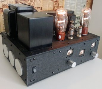
I just wanted to thank PB and PJ for their input on the parafeed topology, this amplifier was completed in April.
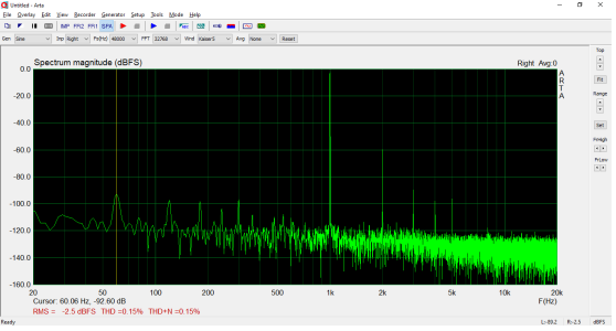
Below is an FFT at 350mV into 300 ohms. Not sure why I didn't measure at 1mW into 300ohms at the time, but this is what I have. I think this is what I determined to be listening volume with my headphones.
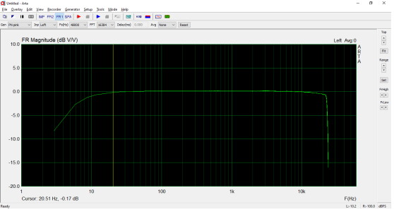
Also the FR plot, I ended up using two 3.3uF Rike Audio S-Cap-2 aluminum foil PIO caps in parallel, after my experiments with the Solen caps, so 6.6uF total on the output.
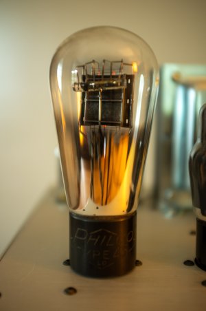
I put some globe 45 tubes in this amplifier as well, they are very nice sounding tubes, I got them for a bargain on eBay since they were untested. One had a filament to grid short, I whacked the tube a few times and broke the short, they test over 100% emission on my Jackson 648-R.
Below is an FFT at 350mV into 300 ohms. Not sure why I didn't measure at 1mW into 300ohms at the time, but this is what I have. I think this is what I determined to be listening volume with my headphones.
Also the FR plot, I ended up using two 3.3uF Rike Audio S-Cap-2 aluminum foil PIO caps in parallel, after my experiments with the Solen caps, so 6.6uF total on the output.
I put some globe 45 tubes in this amplifier as well, they are very nice sounding tubes, I got them for a bargain on eBay since they were untested. One had a filament to grid short, I whacked the tube a few times and broke the short, they test over 100% emission on my Jackson 648-R.
Attachments
Looks good!
L0rdGwyn
New member
Thanks! I'm very happy with it, I appreciate the help, every amp build is a learning experience. I'm working on something truly insane now....
It is a three-stage all DHT class A2 hybrid amplifier. Gain stage is a CCS loaded 841 (high mu cousin of the 801A) with filament bias, cap coupled to the second stage which is a transistor source follower buffer, which is direct coupled to the grid of the output stage, a fixed bias 801A with an A2 bias point (420Va, -20Vg, 40mA Ia) into a 11K:8ohm OPT. The source follower drives the grid of the 801A far into A2 territory, the grid swings from around +50V to -100V for roughly 6W into 8ohms out of the 801A! I just finished the prototype, sounds darn good too.
Anyway, thanks again.
I thought it was a #45 amp?
L0rdGwyn
New member
Wow, that looks incredible! It is an A1 design with a choke input supply?
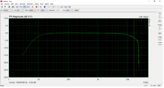
Yeah, not getting the same FR results with the 11K:8ohm traffo HA! Bass extension is great but I do have some HF rolloff, -3dB at 16.5kHz, 20kHz is at -4.4dB. Below is the FR at 1W into 8ohms.
Even with the HF rolloff, it sounds very good and the bass definition is fantastic.
Yeah, not getting the same FR results with the 11K:8ohm traffo HA! Bass extension is great but I do have some HF rolloff, -3dB at 16.5kHz, 20kHz is at -4.4dB. Below is the FR at 1W into 8ohms.
Even with the HF rolloff, it sounds very good and the bass definition is fantastic.
Attachments
No, that's A2 biased (about 0V on the grid). It is a choke input supply since the 801A doesn't need a whole ton of voltage to make a decent amount of power. I ran it at 325V/60mA.