C2A 270Ω 5Ws are glowing orange from heat!

kurogle

New member
Hi - Please tell me it's not hopeless... I've built 2 Cracks w speedballs successfully and went into the crackatwoa maybe too confident. Pretty bummed out now.

I made two initial dumb mistakes:
  1. I spray painted the wrong side of the chassis. Before the paint fully cured, I scraped it away down to bare metal around all of the holes and openings.
  2. I initially connected the (2) 270Ω 5W wirewound resistors to 33L instead of 32L.
When I began my first voltage check after completing the board, the 270Ω 5Ws started smoking so I unplugged the C2A within 20 seconds of starting the test. After this is when I noticed they were connected to 33L instead of 32L.

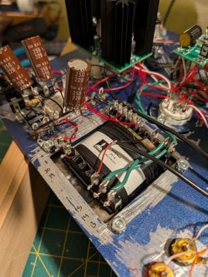
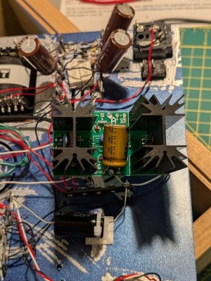
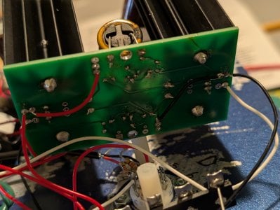
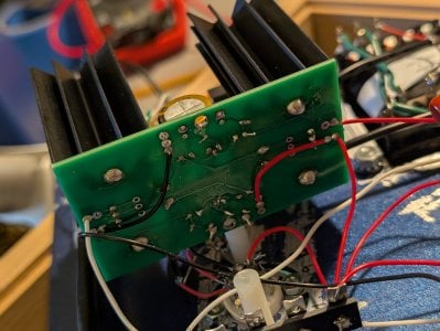
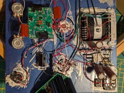
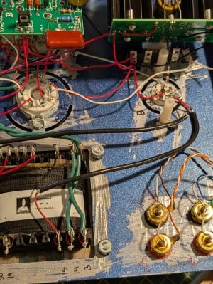
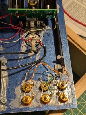
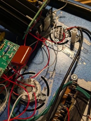
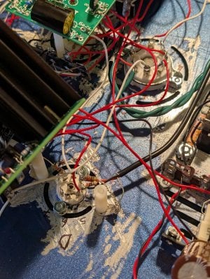
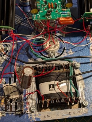
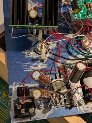
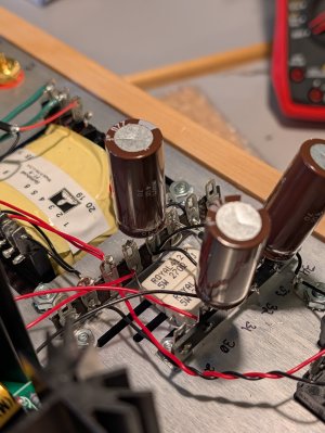
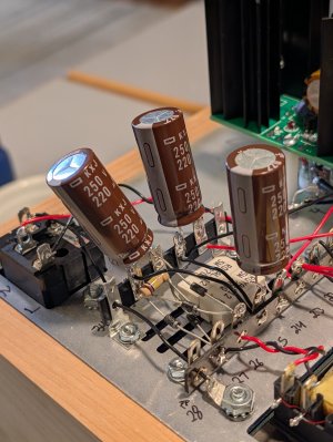
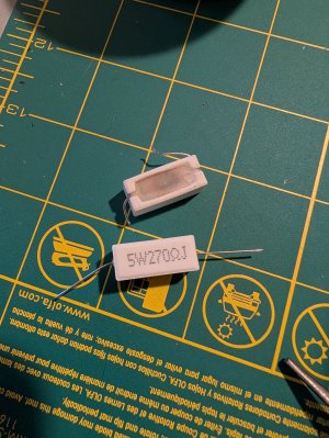
I realized the two 270Ω 5Ws were cracked from the overheating so I purchased 2 new 270Ω 5W wirewound resistors online and the leads were a bit shorter than what bottlehead provided so I soldered them together to a small black cable to connect to 32L. The pictures attached are with the new resistors.

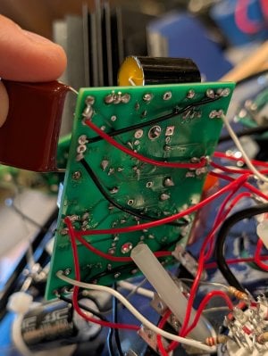
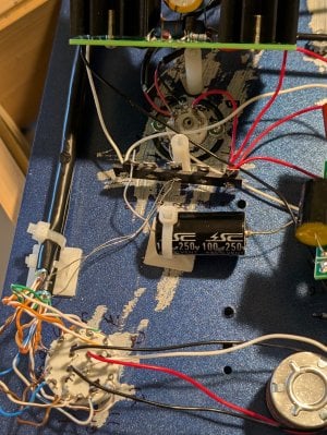
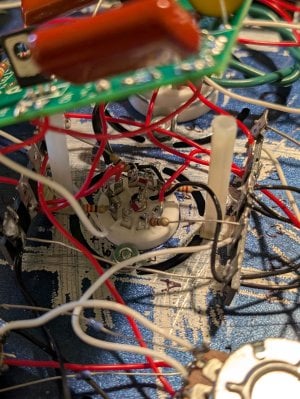
I had to pull out and reinstall all of my UF4007 rectifiers to accomplish this, so they look messy now but I triple checked they are all connected to the correct spots and in the correct direction.

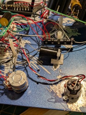
After this, I went back through all C2A instructions to confirm there were no other wrong connections, and re-soldered any connections that looked poor.

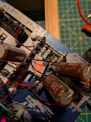
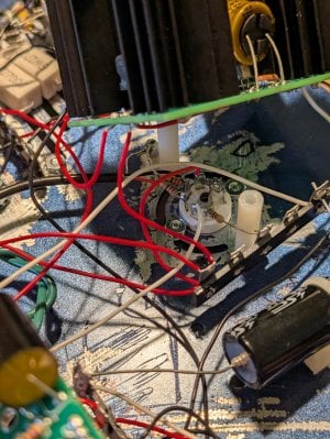
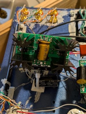
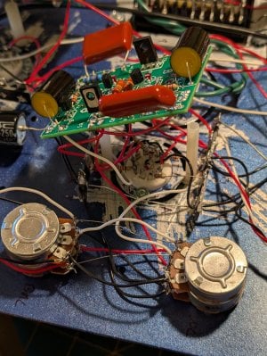
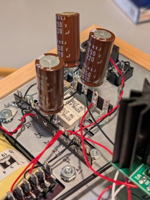
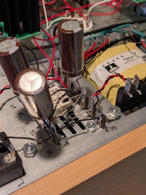
For my voltage test attempt #2, all tubes glowed and all HLMP 6000 LEDs glowed (the LEDs on the two high current boards were much brighter than the very dim LEDs on the low current board). This is when I noticed the (2) new 270Ω 5Ws started to glow orange within 10 seconds. I quickly took the picture attached before immediately unplugging the C2A.

I never got to the point to be able to do the voltage test either time.

Let me know if you have any thoughts. Thank you.
 

Attachments

  • PXL_20250918_003614316.jpg
    PXL_20250918_003614316.jpg
    1.1 MB · Views: 39
  • PXL_20250918_003533403.jpg
    PXL_20250918_003533403.jpg
    1.1 MB · Views: 33
  • PXL_20250918_003418140.jpg
    PXL_20250918_003418140.jpg
    795.1 KB · Views: 32
Did the amp pass resistance checks? Can you post more pictures from around the amp?
 
I would suggest doing a parts purchase request for new terminal strips, 270 ohm resistors, and caps to go by the power transformer. The UF4007s have to be positioned relatively perfectly as they are in the manual so that none of the leads touch, and we still have 270 ohm 5W resistors with long leads available so you can get that patched up properly. The component leads need to be trimmed back quite a bit more than they are now, and the parts need to be attached (bend the leads up and around the terminals) before they are soldered. Those 220uF caps will be especially prone to breaking loose if you just have the leads poking straight through the terminal and are only relying on solder to keep them in place.

Without seeing the rest of the amp, it's tough to know what's causing the problem you're experiencing.
 
Sounds good I will definitely do a parts exchange. Here are a bunch more photos of the amp. Let me know if you need to see anything closer and if this reveals anything else wrong. I will post again now with ago additional photos due to upload limit.
 

Attachments

  • PXL_20250918_115339660.jpg
    PXL_20250918_115339660.jpg
    2.4 MB · Views: 24
  • PXL_20250918_115346039.jpg
    PXL_20250918_115346039.jpg
    2.2 MB · Views: 14
  • PXL_20250918_115355367.jpg
    PXL_20250918_115355367.jpg
    1.8 MB · Views: 15
  • PXL_20250918_115408306.jpg
    PXL_20250918_115408306.jpg
    1.1 MB · Views: 14
  • PXL_20250918_115419506.jpg
    PXL_20250918_115419506.jpg
    1.4 MB · Views: 12
  • PXL_20250918_115428138.jpg
    PXL_20250918_115428138.jpg
    1.1 MB · Views: 12
  • PXL_20250918_115436518.jpg
    PXL_20250918_115436518.jpg
    1.4 MB · Views: 10
  • PXL_20250918_115443849.jpg
    PXL_20250918_115443849.jpg
    1.2 MB · Views: 10
  • PXL_20250918_115503968.jpg
    PXL_20250918_115503968.jpg
    1.9 MB · Views: 8
  • PXL_20250918_115512483.jpg
    PXL_20250918_115512483.jpg
    2.9 MB · Views: 8
Part 2 of additional photos. Thank you again.
 

Attachments

  • PXL_20250918_115247150.jpg
    PXL_20250918_115247150.jpg
    2.3 MB · Views: 6
  • PXL_20250918_115251626.jpg
    PXL_20250918_115251626.jpg
    2.2 MB · Views: 4
  • PXL_20250918_115255750.jpg
    PXL_20250918_115255750.jpg
    2.4 MB · Views: 4
  • PXL_20250918_115301059.jpg
    PXL_20250918_115301059.jpg
    2.2 MB · Views: 3
  • PXL_20250918_115320427.jpg
    PXL_20250918_115320427.jpg
    2.2 MB · Views: 1
  • PXL_20250918_115328729.jpg
    PXL_20250918_115328729.jpg
    2 MB · Views: 1
  • PXL_20250918_115334506.jpg
    PXL_20250918_115334506.jpg
    1.6 MB · Views: 1
  • PXL_20250918_115242923.jpg
    PXL_20250918_115242923.jpg
    2.1 MB · Views: 2
  • PXL_20250918_115239501.jpg
    PXL_20250918_115239501.jpg
    1.9 MB · Views: 10
How were the resistance checks?

Getting a proper pair of side cutters will really help clean up all those leads sticking out. I typically recommend the CHP-170 from Hakko.
 
Hi Paul - I put fixing my first Crackatwoa repair on hold and picked up a second C2A (I wanted two anyway, and if I can fix this one maybe it’ll help me understand the first).

I also got proper side cutters and did a better job making sure component leads are fully attached before soldering.

But having issues with this build now — similar overheating symptoms at first.

All resistance checks passed. When I plugged in for the first voltage test after completing the build:
  • All LEDs lit (some bright, some dim)
  • I 270Ω 5W resistors started to overheat before I could take any readings, so I unplugged immediately. They didn’t glow red like my first build, but maybe after some time they would've.
I went through the manual and re-confirmed all wiring locations and re-flowed all connections. This is my 4th build (2 Cracks / 2 C2As), so I thought my soldering was solid, but maybe not.

After that, I powered back on to take voltages. This time the 270Ω 5W resistors didn’t heat up, but only half of the LEDs lit.

These LEDs did not light up:
  • both LEDs on the "A" side of the Low Current C4S Board were not lit
  • all four LEDs on the High Current C4S Board on the RCA input side of the amp were not lit
  • the LED connecting A8 to the center lug of the A socket.
All other LEDs lit up.

Since the 270Ω 5Ws weren't overheating, I did a quick voltage check before turning it off:

Low Current C4S:
IA - 0
OA - 0
KregA - 1.4
bRegA - 0
IB - 150
OB - 66
KregB - 5
bRegB - 150

High Current C4S (headphone output side):
IA - 202
OA - 150
bA - 0
IB - 0
OB - 90
bB - 150

High Current C4S (RCA input side):
IA - 0
OA - 0
bA - 0
IB - 0
OB - 0
bB - 0

With half the boards at 0V and the corresponding LEDs out — does that help narrow the fault? If you suggest getting replacement parts for this build as well and re-doing any sections, I will. Possible one of the 270Ω 5Ws got fried maybe?

I attached photos of the high-voltage power supply area. Let me know if you’d like others.

Note: instead of the supplied 100µF/250V caps, I installed Mundorf MCap EVO Aluminum Oil 100µF/350V caps taken from one of my Cracks. I tested their capacitance first (99.9µF). Please let me know if that could be an issue.

Thank you for all of your help!
 

Attachments

  • PXL_20251207_154901630.jpg
    PXL_20251207_154901630.jpg
    1.3 MB · Views: 6
  • PXL_20251207_154824738.jpg
    PXL_20251207_154824738.jpg
    1.1 MB · Views: 5
  • PXL_20251207_154847405.jpg
    PXL_20251207_154847405.jpg
    1.1 MB · Views: 6
  • PXL_20251207_154810113.jpg
    PXL_20251207_154810113.jpg
    1.3 MB · Views: 8
The 0V at IA tells me either the wire going to that terminal from the power supply is broken, or one of the 270 ohm resistors is now open.

The 66V at the OB pad on the low current board makes me wonder if you have a transistor installed improperly on that board.
 
That's for the quick response Paul.
The low current board OB is supposed to be 60-90V so I think I'm in range for that one?
 

Attachments

  • Screenshot_20251207-133802.png
    Screenshot_20251207-133802.png
    645.3 KB · Views: 15
It's worth double checking the transistors just to be sure. But otherwise yes, half of your amplifier is working properly.

-PB
 
Double-checked the transistors on the low current board and they look correctly oriented, with no missing solder joints.

I removed the 270Ω resistor that was feeding the red wire to the side of the amp that wasn’t lighting up and was showing 0V. The bottom of the resistor looks fried (photo attached) - or is this discoloration normal? I can see through the grille that the 'working' 270Ω resistor is slightly discolored but not as bad as the fried one.

I replaced it with another 270Ω 5W wirewound resistor I had on hand (also in the photo — not from Bottlehead). When I powered the amp back on, all the LEDs on the C2A were back to being lit up! But this resistor quickly started overheating, so I shut it down.

Is there anything upstream of the 270Ω resistors that could cause it to overheat like that?

It can't be a coincidence that my first C2A had the exact same issue, right? The manual I received is Crackatwoa_Manual_06-14-20-uuajau.pdf. Is that the most current version?

Thanks again so much Paul
 

Attachments

  • PXL_20251207_194933212.jpg
    PXL_20251207_194933212.jpg
    2 MB · Views: 19
  • PXL_20251207_195338867.jpg
    PXL_20251207_195338867.jpg
    1.8 MB · Views: 23
If you suspect a resistor is bad, you can take it out and measure its resistance to see if it's still 270 ohms.

No, things that are upstream of that resistor aren't going to cause it to burn up.

I would be almost positive that you have an issue with the high current C4S board fed from that half of the power supply.
 
I went through the manual 2x again and can't find anything wrong :(
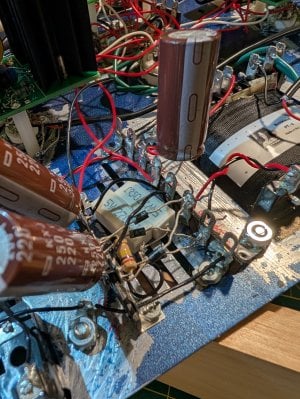
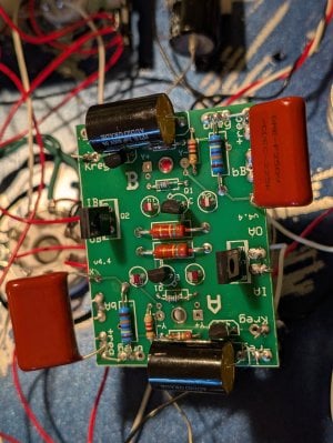
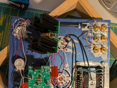
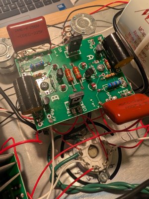
. Everything on the C4S boards looks to be correct and not backwards. I'm guessing it's something dumb I did wrong but really can't figure it out.
Do you offer a repair service that I could send the amp to you? I'm at a loss for what to do.
 
Back
Top