Wrong voltage on speedball big board [resolved]

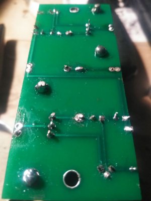
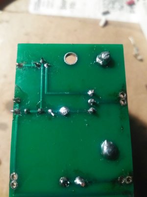
I redid all the joints on the big board and reattached it, readings are

OA - 119
OB - 218
G - 0
B+ - 227

and the same two LEDs aren't lighting up :/
 
There's a broken wire from the board to the socket, or a miswire from the board to the rest of the circuit, or there's still a bad solder joint on the board itself.  The B+ being high and OB being high means that half of the board just isn't allowing half of the 6080 to draw current.
 
I looked at the board and the wiring back to the circuit and I can't see anything obviously wrong. It seemed so close to working now I'm not sure what to do
 

Attachments

  • IMG_20200913_145534.jpg
    IMG_20200913_145534.jpg
    88.5 KB · Views: 16
  • IMG_20200913_145549.jpg
    IMG_20200913_145549.jpg
    91 KB · Views: 16
How's that? Good to go back into the circuit?
 

Attachments

  • IMG_20200913_165353.jpg
    IMG_20200913_165353.jpg
    75.5 KB · Views: 8
  • IMG_20200913_165405.jpg
    IMG_20200913_165405.jpg
    72.9 KB · Views: 5
On each leg of each TIP50 transistor, I would hold your soldering iron on there and count to ten, then move on to the next leg.  You can do one leg of the A transistor, then a leg of the B transistor, then back to A, etc. switching off to keep the transistor from heating up too much.

It also looks like maybe one end of one of the 47K resistors needs some more heat and solder.
 
OK, so I did all of that, put the leads on the board again, go to do resistance checks, then OB gives me around 4.6 megaohms, and OA doesn't read anything.
 
One side is reading 4,500,000 ohms and the other side is reading so high your meter can't determine what it is.

The manual says OA and OB on the big board should be several hundred thousand ohms at minimum.

I'm not seeing what the issue is here, I would move on to checking the voltages.
 
Trying my best lol, this pcb soldering stuff isn't as easy as the stripping wires and soldering them to terminals sticking up ig...
 

Attachments

  • IMG_20200913_202230.jpg
    IMG_20200913_202230.jpg
    62.3 KB · Views: 9
  • IMG_20200913_202218.jpg
    IMG_20200913_202218.jpg
    69.7 KB · Views: 12
I've been using this 60/40 rosin core radioshack solder that's been lying around in my garage forever throughout the whole amp, as for irons I've used this bluepoint soldering gun for about 95% of the time except for just recently with the pcbs I started using this weller iron (I like the soldering gun better).
 

Attachments

  • IMG_20200913_204724.jpg
    IMG_20200913_204724.jpg
    102.1 KB · Views: 4
  • IMG_20200913_205100.jpg
    IMG_20200913_205100.jpg
    72.4 KB · Views: 6
  • IMG_20200913_205142.jpg
    IMG_20200913_205142.jpg
    44.1 KB · Views: 3
  • IMG_20200913_205153.jpg
    IMG_20200913_205153.jpg
    70.8 KB · Views: 5
OK, reflowed with the gun put the board on again, resistance check, meter didn't read anything, voltage check

OA - 117
OB - 220
G - 0
B+ -226

 
Well, at this point I would suggest sending it in for repair and I can fit a new board on it for you, or you can e-mail replacementparts to ask for a new board, or you can pull the LEDs and the two transistors on the bit that's not conducting and replace them.

Board rework isn't super easy though.

It's moderately probable that the big lump of solder that I saw bridging the connections on one of the LEDs would've required enough heat to melt the LED itself, and it may be damaged.  Some meters have a diode check setting that can allow you to measure them, and they should show about 1.57V in one direction and nothing in the other.
 
Back
Top