You are using an out of date browser. It may not display this or other websites correctly.
You should upgrade or use an alternative browser.
You should upgrade or use an alternative browser.
Tubes are not glowing
- Thread starter zlib
- Start date
Yeah, that could present a problem down the road if the wrapping on the cap becomes damaged.zlib said:Oh, and now one of those capacitors' bodies touches one lug of heat sinks (where TIP50 transistors are installed). Is it bad?
Your voltages are now varying wildly, and you seem to have a bit of a short now.
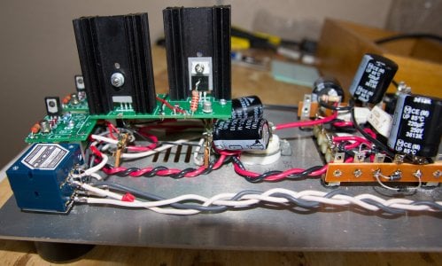
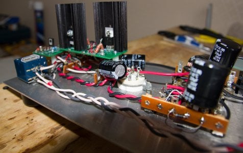
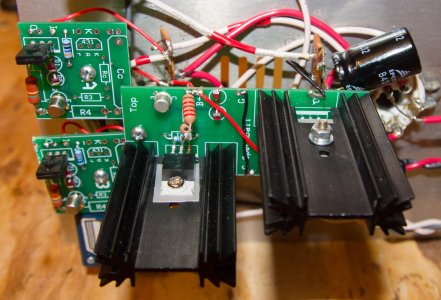
Can you post some photos of your build?
I moved the capacitor's body a little away from that lug but the voltages didn't change. Here are more precise voltages (done with digital meter):
1 - 38
2 - 43
3 - 0
4 - 42
5 - 2.3
6 - 0
7 and B3 - 34
8 - 0
9 and B6 - 0.1
10 - 0
Photos are in attachments.
1 - 38
2 - 43
3 - 0
4 - 42
5 - 2.3
6 - 0
7 and B3 - 34
8 - 0
9 and B6 - 0.1
10 - 0
Photos are in attachments.
Attachments
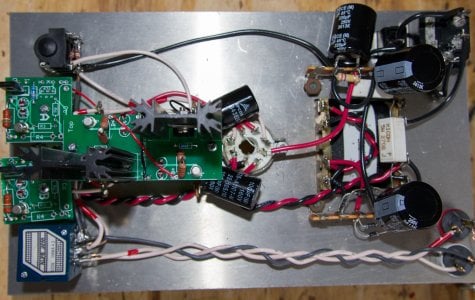
It looks from the photos like potentially our TIP50 transistors are not mounted properly.
Please go back and carefully consult the manual, verify the steps, and check to see that your hardware is where it should be.
Please go back and carefully consult the manual, verify the steps, and check to see that your hardware is where it should be.
What exactly is wrong with TIP50? I have inspected them 4 times already and can't see anything different from the manual.
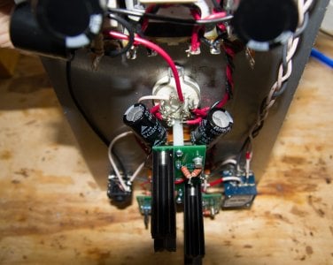
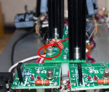
I have mentioned before the only potential problem I see: I didn't leave the space from one 2N2222A transistor's body to PC board (see the attachment). Is it really a problem?
I have mentioned before the only potential problem I see: I didn't leave the space from one 2N2222A transistor's body to PC board (see the attachment). Is it really a problem?
Attachments
fullheadofnothing
Moderator
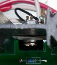
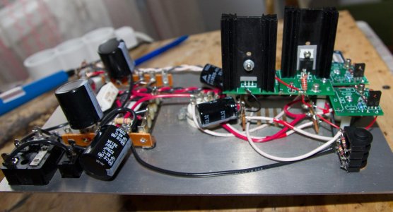
From the top-down shot that you posted, it looks like there are washers that aren't where they are supposed to be.
Go back to the first photo on page 15 of the Speedball manual, then look at your boards just to be sure.
Go back to the first photo on page 15 of the Speedball manual, then look at your boards just to be sure.
I tightened the screws on heat sinks but after about a minute the LEDs turned off and my voltages returned to previous low values everywhere. About that fiberwasher... It is not actually a fiber, it is a platic one but it doesn't conduct the current, right? I don't remember now if I had fiber washers in speedball kit or not but those plastic ones are the ones I have now anyway. Is it a problem?
Attachments
The plastic washers are insulators. If they aren't in properly, they can't insulate.
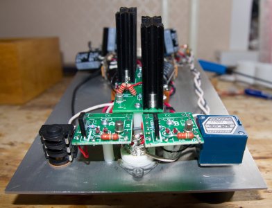
I rolled up the screws with cotton thread and now my meter shows nothing between the screw and middle leg of TIP-50 transistor. The voltages seem OK too, all LEDs are glowing (but the LEDs on small PC boards are glowing less than the others).
Now I have the noise in left channel. The noise changes in time... When I turn the amp on I hear loud noise in left channel, after about 10-15 seconds it sounds way more quiet (some people don't notice it at all at this stage) and then it produces BOOMs occasionally. The noise is not related to the volume level. Once again the only potential problem I see is that 2N2222A transistor which was soldered without leaving the space between transistor body and PC board. I tried another 12AU7 but the noise is still present. Could you help me, please?
Now I have the noise in left channel. The noise changes in time... When I turn the amp on I hear loud noise in left channel, after about 10-15 seconds it sounds way more quiet (some people don't notice it at all at this stage) and then it produces BOOMs occasionally. The noise is not related to the volume level. Once again the only potential problem I see is that 2N2222A transistor which was soldered without leaving the space between transistor body and PC board. I tried another 12AU7 but the noise is still present. Could you help me, please?
Hi,
Your solder joints look rather matte and convex; they should be shiny and concave. Perhaps you are not applying enough heat when soldering. This can create cold joints and cause the noise you are hearing in one channel. Make sure that your iron touches all the parts to be soldered and when the lead is melted, count to three and remove your iron.
Richard
I agree, cold joints will cause that kind of noise.
OK, I resoldered almost every joint and made some space between PC board and 2N2222A transistor's body. Now my Crack sounds very good, but during the first 30 seconds after turning on there are some noisy cracks in left channel, after that everything is normal. I measured the voltages and found the difference in voltages between terminals 7 and 9:
7 - 108
9 - 98
Is it still cold joints or something else? In the past when I had problems with left channel the terminal 9 voltage was around 118.
7 - 108
9 - 98
Is it still cold joints or something else? In the past when I had problems with left channel the terminal 9 voltage was around 118.
The voltage at 9 dropping by 20V suggests that you have fixed a flaky solder joint.zlib said:7 - 108
9 - 98
Is it still cold joints or something else? In the past when I had problems with left channel the terminal 9 voltage was around 118.
If you still have noise, there are likely still other cold joints.
Rocketman248
New member
zlib said:I rolled up the screws with cotton thread and now my meter shows nothing between the screw and middle leg of TIP-50 transistor. The voltages seem OK too, all LEDs are glowing (but the LEDs on small PC boards are glowing less than the others).
I would shoot an email to Bottlehead's replacement parts department and get the proper transistor mounting kit. The thread may work for now, but that seems pretty sketchy to me.