Troubleshooting Crack-a-two-a Resistance Checks

dheffer

New member
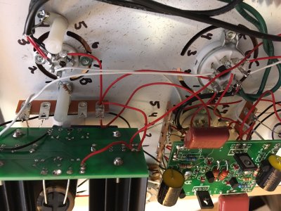
Finished building my crack-a-two-a.  Going through and running resistance checks, I have one that is off.

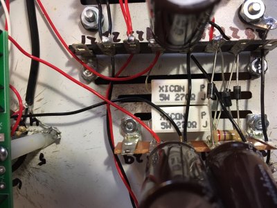
Terminal 5 reads 4.3K ohms (vs. 2.2K).  Terminal 15, on the other side, correctly reads 2.2K.

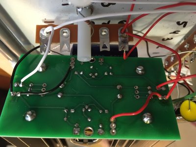
I've tried re-soldering and checking where I can, but can't seem to see anything else to try.  Any helpful hints from the experts on what to focus on?
 
Both terminals 5 and 15 are wired to the headphone jack.  At the tip and the ring connections on the headphone jack, there's a 2.2K resistor to the sleeve (ground) connection on the headphone jack.  If the 2.2K resistor is there and properly soldered in, you'll get 2.2K to ground from 5 and 15.  If you have the resistors improperly connected (say you have a 2.2K resistor between tip and ring), then you could easily get 4.3K at one of the terminals (and a ton of signal bleed between channels). 

-PB
 
Caucasian Blackplate said:
Both terminals 5 and 15 are wired to the headphone jack.  At the tip and the ring connections on the headphone jack, there's a 2.2K resistor to the sleeve (ground) connection on the headphone jack.  If the 2.2K resistor is there and properly soldered in, you'll get 2.2K to ground from 5 and 15.  If you have the resistors improperly connected (say you have a 2.2K resistor between tip and ring), then you could easily get 4.3K at one of the terminals (and a ton of signal bleed between channels). 

-PB

Hey - thanks - that's exactly it.  I put the 2.2K between the tip and ring.  I was focused on everything upstream (from the cap backwards) and missed that.  Appreciate your help.  Time to head to radio shack!
 
If you need new resistors, anything between 1.2K and 2.5K is going to be fine.  Wattage is extremely unimportant here.
 
Thanks - I was actually able to save the existing one.

Running through my voltages check, wanted to see if anyone had any advice on where to turn -

- All tubes illuminate
- LEDs on A side only of High Current boards are lit
        IA = 217V
        All others are 0V
- Low current board is unlit / no voltage
- "A" tube socket LEDs are unlit

Guessing it's wiring around the "A" tube socket (6088) rather than the high-current boards - only a guess though.  Any guesses as where to best focus on where the error might be?  That last tip really saved my butt  8)
 
Check the jumpers on the high current C4S boards.  If OA is 0V, then you may have a jumper that's grounding out the output voltage.  If you'd like a second set of eyes, feel free to post photos of your build and we may be able to spot the error.

Also, if OA on both sides is 0V, then the error has likely been replicated in both channels.

-PB
 
Finally got around to spending some time on trying to troubleshoot... Tried re-soldering on every point on one of the high current boards, but no luck... Both high current boards show the same issue:

IA = 220V
OA = 0V
LEDs on the "A" side
No LEDs lit on the "B" side
IB = 0V
OB = 0V

I've attached photos of one of the high current boards.  Please let me know if any other views might help!  Appreciate any advice I can get!  Thanks
 

Attachments

  • image4.JPG
    image4.JPG
    846.4 KB · Views: 65
  • image3.JPG
    image3.JPG
    856.9 KB · Views: 47
  • image2.JPG
    image2.JPG
    1,016.7 KB · Views: 55
  • image1.JPG
    image1.JPG
    985.9 KB · Views: 49
Looks like you've got a 147K ohm resistor in the R1 Position on the A side.  Should be a 13 ohm part.  Page 45 in the manual.
 
Thanks, thats a huge help!  I'll blame it on being partially color blind  ;D

I need to buy 2 new 147K parts, as the metal leads are clipped to close to work on the low voltage boards (the holes are much farther apart).

I'm having trouble finding exactly what I need - any advice on where to purchase?  I seem to find plenty of 1/2W metal film resistor, but not in the 147K variety.  Just can't seem to track down the right thing.  Would a 150K ohm 1/2W carbon film resistor be OK/close enough?
 
Jump on Mouser.com and search:
271-13-RC
MF1/2CC1473F

Those should be the exact (or close) parts that came with your kit.

Best,

-T
 
So... blast from the past here, I finally got around to ordering the replacement resistors.  Just took me four years  ;D

Have everything installed and pass resistance checks.

Bad news, I get some funky voltage readings:

Low Current C4S

IA          337V      335V
OA        330V      180V
kRegA    14V        10V
bRegA    336V      335V

High Current C4S

IA          407V    410V
OA        335V    335V
bA          0V          0V

IB          0V          0V
OB          220V      325V
bB          335V      335V

Any advice on where next to troubleshoot?
 
Having such high voltages means you likely have a broken wire (or a bunch of broken wires).  We just went through a similar exercise with another C2A builder who had a broken wire between the power supply (where the 220uF caps are) and one of the high current C4S boards. 

He then continued to have enough problems that he sent the amp in for repair and I will be working on it shortly. ]

What DC voltage do you see between 24 and 25?  How about 30 and 31?

 
Paul Birkeland said:
What DC voltage do you see between 24 and 25?  How about 30 and 31?

Apologies for the very long delay, again :)

24 = 426V
25 = 0V
30 = 428V
31 = 0V

I've done a visual check for broken wires and nothing stands out.

Let me know if there are other checks or hints as to solving my issue, or if requesting a repair service is the way to go.

Thanks again!
 
No, you would put one probe on 24 (black) and one probe on 25 (red), then report that voltage, then repeat for 30/31 (and may as well do 33/32 while you're at it).

You very likely have a loose, broken, or poorly soldered black wire in your amp.
 
I spent a few hours trying to re-solder everything, focusing on the black wires.  I couldn't find anything that seemed glaringly off, but ended up breaking a couple wires in the process, so worked to replace those.  At this point I fear I'm just making matters worse.  I put together a crack+speedball easy enough but I may have bitten off more than I can chew :) 

Would I be a good candidate for the repair service?  Is that still something offered?

Thanks again for all the tips/advice!
 
I'm not taking any additional repairs till after the new years.

You 10000% have a black wire that's not doing its job, that's why you appear to have an insane amount of DC voltage but your power supply caps that aren't rated for that voltage aren't exploding.

If you have a bunch of broken wires in your kit, please replace them all and consider looking into a different wire stripper to help accomplish that.  If necessary you may want to contact replacementparts(at)bottlehead(dot)com about getting an extra wire bag for your kit so you have some surplus to work with.
 
Back
Top