You can use two 1N5820 diodes to make a full wave rectified supply to feed the #45, then a small value resistor, then a 10,000uF cap. The value of the resistor and the actual 10,000uF cap you use will interact together to result in an optimal value, but I think you could start with a 0.22 ohm/3+W resistor to see what happens.
You are using an out of date browser. It may not display this or other websites correctly.
You should upgrade or use an alternative browser.
You should upgrade or use an alternative browser.
The Phantom SR45 Build - Snow Creek Shuttle Episode 1-A Bottlehead Saga
- Thread starter ssssly
- Start date
Paul Birkeland said:You can use two 1N5820 diodes to make a full wave rectified supply to feed the #45, then a small value resistor, then a 10,000uF cap. The value of the resistor and the actual 10,000uF cap you use will interact together to result in an optimal value, but I think you could start with a 0.22 ohm/3+W resistor to see what happens.
Sounds like a wonderful idea. And I have everything but the resistors.
But i needed to order parts this week anyway.
What would you suggest as a reasonable range of resistors to buy to dial it in? Given the 10,000uf caps I have are the Xicons from a BeePre.
I'd buy a 0.15, 0.2, and 0.3 or so ohms. If you're ordering resistors, maybe look at getting a pair of 10,000uF 25V caps. Those caps will live a pretty hard life in that position, so a physically larger cap with higher ripple current capabilities will live a lot longer.
Dang it. I'm going to find something to do with those BeePre parts.
Though I suppose I should just knock it up and see what the real world voltage drop and ripple is with those diodes first anyway. Spec sheet says .475v peak drop which would only leave me with ~2.2v. So I'm guessing not much voltage left to play around with under load. And fingers crossed that real world drop is under .6v combined.
And I should probably get the scope and boards out anyway. Need to design and test the voltage doubler for the HV side.
And now I'm sitting here thinking: I need to order stuff anyway, why not try to throw pi filter in there. Or model it up and see if I can do a constant current heater to prolong the life of the 45s. In other words why I always have 10 projects going at once.
Right. Order some good 10000uf filter caps and resistors. Build it and see what it sounds like.
Which diodes did you select for the filament supply?
I'm not entirely certain that constant current regulation for a filament actually prolongs the life of a tube, but YMMV.
I'm not entirely certain that constant current regulation for a filament actually prolongs the life of a tube, but YMMV.
Paul Birkeland said:Which diodes did you select for the filament supply?
I'm not entirely certain that constant current regulation for a filament actually prolongs the life of a tube, but YMMV.
1N5820s.
I'm not convinced either way either. And upon a minute of further thought, the circuit I was thinking of would require a second heater in series or a dummy load. So if I decide to try the current route, it would be in a different form.
I'm just going to build the full wave rectifier with over specd caps, see what I get for ripple and turn on voltage and go from there. I want to get them built and see what they sound like more than I want to fiddle with theoretical benefits at this point.
Oh, there is a connection labeled ground on the board you made me that is connected to the center tap in the hookup instructions. But that was for a PT-2. Would you still suggest connecting it to the center tap at terminal 10 on the PT-7?
From my incomplete understanding of the differences between the two transformers I was thinking ground.
The PT-7 has only one secondary. If you ground it, that will zero bias the #45 tube and things will go awry in a huge hurry. That ground connection should connect to your audio ground and the heater winding floats (it will be biased up to the bias voltage of the #45 tube since it's serving as the filament winding).
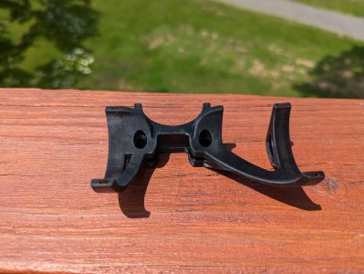
Why...thank you. I tried to make it aesthetically pleasing as well as functional. Unfortunately the Parafeed cap didn't quite clear. It's stuffed tight into the corner between the plate choke and the SR PCB.
Moved the bracket over a couple mm and printed V5 last night. In the ultrasonic now.
And if you think that's cool wait until I get to the Paramour rebuild portion of the shuffle. I'm going to do fully 3D printed and electroformed in place wiring.
Moved the bracket over a couple mm and printed V5 last night. In the ultrasonic now.
And if you think that's cool wait until I get to the Paramour rebuild portion of the shuffle. I'm going to do fully 3D printed and electroformed in place wiring.
I mocked up the full wave rectifier for the 45 filament and...I don't really like it. Even with the low Vf of the 1N5820s it just seemed to struggle to provide a stable 2.5v. Set to 2.5v it always wanted to sag and hover around 2.1-2.2. Set to 2.7v around 2.1-2.3v and set to 2.8v it would swing from 2.2-2.8v.
After trying to troubleshoot it for a day I was back to thinking just drop a simple LM317 based constant current heater circuit in there.
Then I remembered seeing some ADP linear voltage regulators that operate around the operating points of the 45 filament. And I came across this little bugger.
https://www.digikey.com/en/products/detail/analog-devices-inc/ADP3339AKC-2-5-RL7/11534905
up to 6v in, 2.5v @ 1.5a out, and only needs 1uf esr agnostic stabilizing caps.
Been staring at the specs for some time now wondering why this won't work a treat and not finding any.
So give it to me...why won't this regulator work?
Heat through a regulator can be problematic. Remember that you need to cover the dropout voltage plus some safety margin.
I don't know what "setting for 2.7" means. You setup the full wave rectifier with a resistor between the rectifiers and the first cap, then adjust the resistor value to get yourself about 2.5V. I would aim for 2.4V-2.6V.
I don't know what "setting for 2.7" means. You setup the full wave rectifier with a resistor between the rectifiers and the first cap, then adjust the resistor value to get yourself about 2.5V. I would aim for 2.4V-2.6V.
I calculated the values for the resistors using my pet AI. Since the resistors were the only variable I referred to them as "set" resistors.i bought a range of resistors from 0.2-0.5ohm. According to the calculations greater than 0-0.2 ohm should result in ~2.7v. I'm now getting ~1.5v loaded with a tube instead of a dummy load.
It says the dropout is only 0.23v at 1.5A for that regulator. Actually why it caught my attention for more than a second. That and the 85/105c ambient/junction temp. Which leads me to believe it could be fine temp wise.
But since I have never seen them used in a heater, I assumed there was something I was missing.
But they are kind of an obscure oop regulator. And the only ones that operate at or near those points. So figured it could just be one of those things where nobody has used one because nobody was looking for one. Since most people would probably just use a transformer designed for what they need.
Paul Joppa
Moderator
Regulated filaments can be tricky to design. It's the one area where PSUD is not as accurate as you might wish, due largely to the inaccurate diode models. You may need to use a Schottky diode rated 15 amps or more. Then you need to subtract the peak ripple voltage from the average DC voltage to keep the regulator from dropping out. I subtract another 10% to allow for power line fluctuations. And the DCR of the transformer (including the reflected primary DCR) adds to the series resistance. And the high voltage winding rectifier/filter adds to the primary voltage losses.
Paul Joppa said:Regulated filaments can be tricky to design. It's the one area where PSUD is not as accurate as you might wish, due largely to the inaccurate diode models. You may need to use a Schottky diode rated 15 amps or more. Then you need to subtract the peak ripple voltage from the average DC voltage to keep the regulator from dropping out. I subtract another 10% to allow for power line fluctuations. And the DCR of the transformer (including the reflected primary DCR) adds to the series resistance. And the high voltage winding rectifier/filter adds to the primary voltage losses.
Certainly seems that way. I have by far the least experience designing anything power supply related. Just not something you come across in mechatronics much unless you are designing large scale industrial, which I don't. And even then it's pretty much just IDing COTS stuff that fits the bill.
I may just slap the PT-2s I have left in these SR-45s and experiment with the PT-7s more when I do my Paramour rebuilds.
I currently have some 6BX7 amps powering the horns in my upstairs system and it's making it near impossible to find a good crossover point. They just sound completely different than the Paramounts powering the woofers. And seem to exaggerated the beamy-ness of the 500b horns.
So I kind of just want to get these built to get the 6Bs out of my upstairs system.
Which voltage is wrong?
The 45 socket voltages were not what I was expecting.
I was expecting A1,2 sub 2vac
A3 ~ 300vac
And the 45 got so hot so quick it kind of alarmed me, given 60x the voltage I was expecting on A1,2.
But if those numbers are good and my expectations were wrong, happy to chalk it up in the win column and see what it sounds like.
I was expecting A1,2 sub 2vac
A3 ~ 300vac
And the 45 got so hot so quick it kind of alarmed me, given 60x the voltage I was expecting on A1,2.
But if those numbers are good and my expectations were wrong, happy to chalk it up in the win column and see what it sounds like.
Similar threads
- Replies
- 0
- Views
- 12K
- Replies
- 2
- Views
- 298