Testing with tubes terminal 7 read 1vdc instead of 170-230

DPetrini

New member
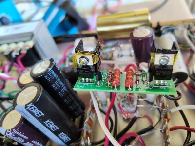
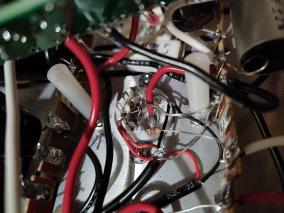
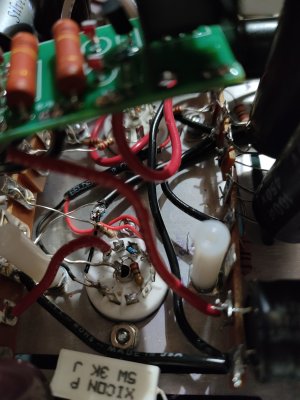
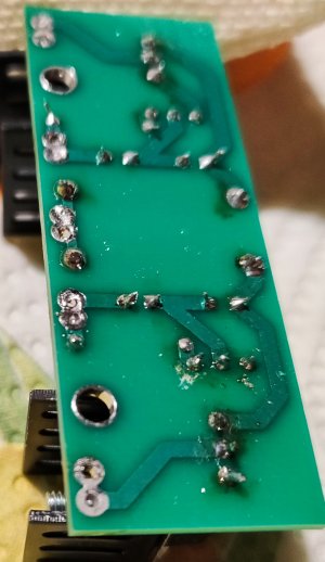
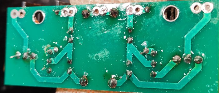
Hi all, any idea where to look for? Apparently all seems done right at First slight. Thanxs

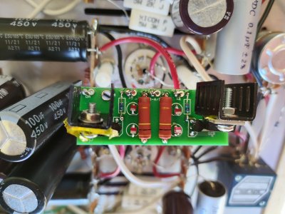
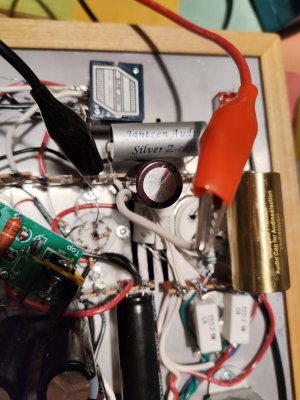
PS Yellow film Is kapton insulating film as could not find the original insulator i might Lost
 

Attachments

  • IMG20230611161118.jpg
    IMG20230611161118.jpg
    4 MB · Views: 15
  • IMG20230611161041.jpg
    IMG20230611161041.jpg
    3.5 MB · Views: 9
  • IMG20230611160439.jpg
    IMG20230611160439.jpg
    3.4 MB · Views: 10
What is your resistance to ground on terminal 7?  Does that red wire touch pins 8/9 on the tube socket?  If it does, that will give you very low voltage on terminal 7.
 
Hi Paul, do you want I Measure the resistance between 7 and 8 with tubes and power on or not? Better double check before making disasters.  I trieds now with no power and no tubes and read 4Mohm and the value continue to increase.

About the cable, i haved distanced the Red cable. After the change still read same voltage(0.961VDC). I can locally order the 4 transistors and i might replace all 4 Just to be sure. Unless other indications from you. Thanxs


Attachments

  • IMG20230612074739.jpg
    IMG20230612074739.jpg
    3.7 MB · Views: 9
Now it looks like pins 1 and 2 on that 9 pin socket shown are touching.

I would not replace the transistors, as an issue like this is the output of the C4S being pulled down below any voltage present on any pins of any of those transistors, so it's likely external to the C4S board.  You can check this by rotating the board 180 degrees and reinstalling it, then see if the low voltage moves to another terminal or stays where it is.
 
I settled the proximity detected by you. Swopped 180 and remeasured . No way both 7 and 14 have same Reading 0.973 and 0.975 on 14.
 
Done It. Used the desoldering gun to make a clean work. Resoldered with my best ...Shining tin Yes.. all...no way ..still 0.9 etcetc.

What can i check else?
 
If you meant to measure from point8 and Oa and from point 8 to OB ,see picture, i have 2mV at start that goes to 0mV in few seconds.
 

Attachments

  • IMG20230613181332.jpg
    IMG20230613181332.jpg
    3.5 MB · Views: 11
Something is very likely not well soldered on the PC board.  Can you take it out and show us the bottom side in better detail?
 
Sure. See enclosed. What about if i get off all components ,clean It and reinstall new batch of 4 transistors? I have received them today from local supply
 

Attachments

  • IMG_20230614_213941.jpg
    IMG_20230614_213941.jpg
    1.4 MB · Views: 9
  • IMG_20230614_213838.jpg
    IMG_20230614_213838.jpg
    858.5 KB · Views: 5
Back
Top