Stock Crack Loud Buzz/Hum Left Channel

Troycnc

New member
Hello,
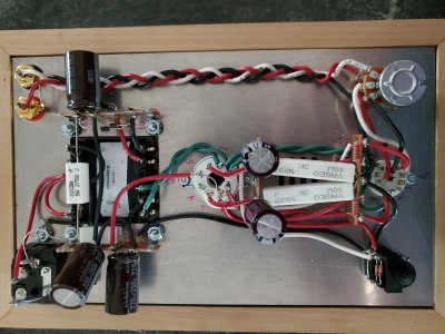
Just built my first Crack and it went pretty well, directions were spot on. All readings are in spec per instructions.
When i first power it on it is dead quiet but within 10 to 15 seconds a hum/buzz starts to build until it is extremely loud and I have to power the unit off. It do'sent matter what the volume is set at.
Spoke with Dan and he recommended re flowing joints. I went back over everything and noticed 1 LED wasn't lit (A3) and Dan recommended  to remove the bad LED and Jump A8 to A3.
Still The Same Hum. Not sure what to do next. If anyone has any ideas I would greatly appreciate it.
Troy
 
If one LED wasn't lit, then your voltages were not consistent with what's in the manual.

I would cut the jumper out and measure the voltages on terminals 1-5, then post them here.  At least one of them will not be correct.
 
Hello Paul,
Thanks for the help. I have removed the jumper I installed from A3 To A8. The voltages are below measured from chassis to terminals 1-5.
1-.209
2-.639
3-0
4-.639
5-40.91
I really appreciate any advice you can give, really looking forward to hearing it run.
Troy
 
Sorry Paul,
Checked them again from 12U to 1-5.
Voltages are out of spec for sure.
1-.135
2-.630
3-0
4-.631
5-40.63
Once again i really appreciate your help
 
So you are saying you have 0.63V on terminal 4 and 40V on terminal 5? 

This can only happen if the string of black wires going across the 6 lug terminal strips, then up to the headphone jack, then over to terminal 3, then to the volume pot and back to the 9 pin socket has a really poor connection or one wire completely missing.

It might help also to post images of your build.

When you mentioned previously that your amp passed all the checks, does that mean you got appropriate voltages at some point?
 
Hey Paul,
I apologize for not explaining it better. I got proper readings from the transformer at the begining of build but never had proper readings from the terminals. I have gone over the wiring again this afternoon and it looks right to me? I have attached a picture if that helps.
Troy
 

Attachments

  • 20190726_170950.jpg
    20190726_170950.jpg
    3.7 MB · Views: 43
Would it not light because of the voltages? What do you reccomend I do waiting for replacement. I was thinking of rewiring the ground path. I'm not sure what to test for to see if that's the problem or if it is a component.
Thanks
 
Troycnc said:
Would it not light because of the voltages?
Yes, your voltages were all out of whack and did not at all indicated a bad LED whatsoever.

Troycnc said:
What do you reccomend I do waiting for replacement.
I would strongly suggest doing absolutely nothing until the replacement LEDs arrive.
Troycnc said:
I was thinking of rewiring the ground path. I'm not sure what to test for to see if that's the problem or if it is a component.
What do you mean by "rewiring the ground path"?  Are you intending to pull out all the black wires and replace them? (please don't).

The problem is not a component.  The problem is almost certainly a bad solder joint or a missing connection that is causing these issues.  I suggested this in a post earlier. 

I've also posted an image from the voltage checks in the manual regarding what a dark LED might indicate...
 

Attachments

  • crack LED info.jpg
    crack LED info.jpg
    61.9 KB · Views: 14
Hey Troy - I'm certain PB will help you get it sorted out - he designed the circuit so no one knows it better. I really recommend continued use of the forum for troubleshooting. The Crack is a fairly simple circuit, so causes of the problem are limited and almost certainly will be found.


I think Deluk's question above is still relevant: your build pic shows two LEDs missing - did you remove them both?  If so, did you keep them? If the leads are still long enough you could try re-installing them and then progress with the troubleshooting.  The first step of which would be to redo the resistance checks, and if that checks out ok, to redo the voltage checks. Post any deviations from the values specified in the manual.


And if it's any consolation: I've spent 20+ hours this past week trying to get a mod to my Beepre to work and am still not there yet - but PB has been helping me and I will eventually get the problem solved. Against my instincts, I've come to accept that the best way of dealing with a problem amp is to take a methodical approach: check one possible cause, and if that's not it, move on to the next, and so on until it's fixed. It takes time, but it gets the problem solved and avoids creating new ones (I've created a lot of "new ones" in the past by fiddling with things that didn't need fiddling with). PB knows the possible causes of the problem and can guide you through the steps to identify which one you're dealing with and how to fix it.


cheers, Derek
 
Troycnc said:
Thanks for taking time to help Paul. I can tell your irritated I'll get it figured out.
I'm still here and happy to help, but it is really helpful to not try to get too far ahead of things, otherwise the process can grind to a halt.  This is super duper common when an LED isn't lit up, and we often get tech help posts that simply provide the information that one of the LEDs isn't lighting, with no additional information.  This is why we put that information in the manual, as there is only one condition that would indicate a damaged LED, and the information you provided did not indicate that. 

Until you can put LEDs back in your Crack and power it up to take some additional measurements, it will be tough to do any other debugging, as the amp can't be powered on in its current state to check for progress. 

One thing I would absolutely recommend doing would be to take your meter and try to read the DC voltage across a 9V battery, just to be sure that the meter is working properly. 
 
Thank you Derek and Paul or the words of encouragement.
I trashed the LED's and should have a new set Wednesday or Thursday. I am taking your advice and will wait on replacement to proceed.
I apologize for getting ahead of myself with repairs, I am real anxious to hear this thing in action.
I will post again once LED's are installed.
I really appreciate you guys help

 
Ok guys had a little vacation and I am back at repairs. I have replaced the LEDs and my resistance checks are as follows

12u to ground is .1

1-1.158m
2-1.113m
3-0
4-1.087m
5-1.085m

6-0
7-2.989k
8-0
9-3.034k
10-0

12-0
13-.905m
14-0

20-0
22-0

B3-2.989k
B6- 3.034k

R-98.5k
L-100.8K
Ground Tab-0

Hope this info helps with whats going on.
Troy
 
Back
Top