A 1.5-3 amp fuse of the appropriate size is fine (5x20).
You are using an out of date browser. It may not display this or other websites correctly.
You should upgrade or use an alternative browser.
You should upgrade or use an alternative browser.
Stereomour Diagnosis Testing or Repair?
- Thread starter audiotecture
- Start date
audiotecture
New member
Paul...finally received my replacement fuses. I retested all of my voltages and there are a few that aren't quite right. Terminal strip 11 = 160V, 15 = 268V, 20 = 160V, C1 = 160V, C2 = 268V, C4 = 160V. Similar to before there is sound coming out of the A side binding posts, but none from the C side binding posts. The PC3 on the C side warms up when the amplifier is turned on, but the PC3 on the A side remains cool.
Heat in the plate choke is determine by the voltage at the HV+ pads on each side of the amp vs. the voltage at pin 2 on each 4 pin socket across the resistance of the plate choke. So for the heat dissipated in the plate chokes to be different, you need voltages on the 4 pin sockets that are completely different from each other or the DC resistances of the chokes need to be way, way different (which would indicate a damaged choke).
I have provided you the instructions before to check for each of these conditions, and you didn't find either issue. I would strongly recommend redoing these checks. For the one plate choke to get hot but not the other, there has to be an accompanying result that indicates why.
So when I went into the manual to see what might be going on with your voltages, I can now tell that your 4 pin socket voltages aren't the same between sides. Seeing 160V at terminal 11 is not a good sign. The rest of these are all kind of a result of that. I suspect that the 5W/10W resistors mounted to the terminal strips on that side of the amp are loose or damaged.
audiotecture
New member
Paul...I took the resistor out and when I tested it, it showed 231.8 ohms of resistance. Looks like my local Microcenter has 220ohm 1/4watt resistors in stock. I should be able to pick them up, replace the existing resistor, and test again tomorrow.
No, put that resistor back!
There is a 5W and 10W resistor connecting between the two 5 lug strips around the 9 pin socket (a 1.6K and a 4.7K). Either one of those is damaged or one of those is not connected (maybe both).
There is a 5W and 10W resistor connecting between the two 5 lug strips around the 9 pin socket (a 1.6K and a 4.7K). Either one of those is damaged or one of those is not connected (maybe both).
audiotecture
New member
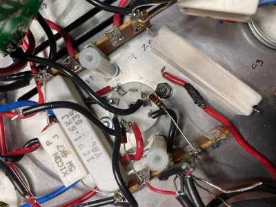
Paul...I think I found the source of the smoke I saw/smelled when I initially powered up the amp with the tubes in the wrong orientation. You can see (in the attached photograph) that the heat from the 10W 1.6K resistor melted the insulation on the red wire between B6 & 14L & singed the socket screw/washer. The 10W 1.6K resistor measures 1.7K ohms of resistance. The 5W 4.7K measures 4.58K. The 220-ohm resistors both measure around 220 ohms of resistance.
Attachments
You can put that all back together, disconnect the "K" wire on the power supply board on that side, then measure DC resistance between ground and pin 1 on the 4 pin socket on that side, then ground to pin 4 on the 4 pin socket on that side (powered off).
-PB
-PB
audiotecture
New member
Paul...Finally had time to put everything back together. I disconnected the "K" wire on the power supply board. Ground to pin 1 and pin 4 on the 4 pin socket are 1.255K ohms (on the side that's not working) For reference measurements on the Ground to pin 1 and pin 4 on the 4 pin socket on the side that is working are 1.168K ohms
You can leave the wire to K disconnected, recheck DC volatges on all four pins on the 4 pin socket on the bad side and report back.
That resistance is totally fine, those resistors are good. There could be something amiss with the wiring to pin 3 of the 4 pin socket that's not allowing for it to get a good ground reference. That is the 249K resistor and the 220 ohm carbon comp grid stopper. Be sure those are well connected.
That resistance is totally fine, those resistors are good. There could be something amiss with the wiring to pin 3 of the 4 pin socket that's not allowing for it to get a good ground reference. That is the 249K resistor and the 220 ohm carbon comp grid stopper. Be sure those are well connected.
You can also swap the 2A3s to see if the voltage issue follows a tube.
audiotecture
New member
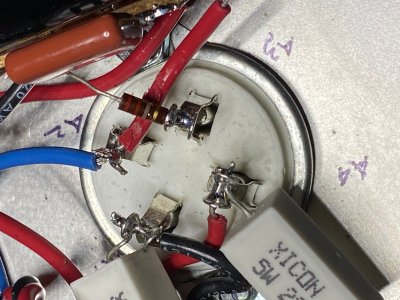
Swapping the 2A3s the reading at A1 is 1.167, A2 * (number keeps getting bigger), A3 248.7, A4 1.167. I don't know if it means anything, but when I did my resistance check, terminal strip 2 & 14 settled at 687K ohms rather than 486K ohms. Terminal strip 7 & 9 are at 15.79 and do not change when the potentiometer is turned. I've also included a photograph of 4 pin socket A. One of the soldering holes broke off at A2 so both wires are soldered to the remaining hole. Not sure if this makes difference?
Attachments
Voltages?audiotecture said:Swapping the 2A3s the reading at A1 is 1.167, A2 * (number keeps getting bigger), A3 248.7, A4 1.167.
audiotecture
New member
Paul...I'm not sure if this is the information you are looking for, but I've detached the black wire from K on the power supply board on the A side and I get the following readings A1 = 59.6V A2 = 362.2V A3 = .008V A4 = 59.5
That's a perfect set of DC voltages. before you had over 100V at A1/A4. Now you can put the K wire back and recheck the DC voltages again.
audiotecture
New member
Paul...I replaced K on the A side of the power supply board and now have the following readings A1 = 59.27V A2 = 360.2V A3 = .007V A4 = 59.30V for reference C1 = 60.57V C2 = 363.1V C3 = .007V C4 = 60.42
Those are working voltages.
audiotecture
New member
Paul...Given the similar measurements on the A & C sides, I attempted to play music and observed the following: If I plug speakers into the A-side and C-side speaker binding posts, sound comes out of the A-side but not C-side. If I take the C-side red cable and touch it to the A-side red binding post, I get sound from both speakers. Touching the C-side black cable to the A-side black binding post does not produce any sound from the C-side speaker.
Turn each hum pot all the way clockwise. Do you hear hum in both speakers?
audiotecture
New member
Paul...yes I hear hum in both speakers.
There's wiring that leaves pin 1 and pin 6 on the 9 pin socket to send signal to each 4 pin socket. I suspect that yours is loose on the side without sound. Since you can hear hum and I'm guessing it's roughly the same level, the 2A3s are operating properly and the output transformer wiring is OK.
If the DC voltages at OA and OB on the 9 pin socket are OK, then that leaves the wiring leaving pins 1 and 6, or possibly signal isn't making it into the 9 pin tube from the input selector and volume pot.
To test the input selector and volume pot, temporarily install a jumper between terminals 7 and 9. This will sum both channels and send that mono signal to both sides of the amp. If your dead channel awakens, then you need to inspect the wiring from the RCA jacks to the selector switch, the selector switch to the volume pot, and the volume pot into the amp. If both channels stop working, that is also an indicator of an issue with the input wiring. If the same channel is still dead, that's an indication of a remaining wiring issue around the 9 pin socket, or possibly the .1uF coupling cap.
-PB
Similar threads
- Replies
- 9
- Views
- 1K