elgringo81
Member
elgringo81 said:I have been back and forth in the manuals and I cannot terminal T1 and T2. Can you please describe them a little so I can locate them?
Could it be that T1 and T2 do not excist in my build since I have version 1.1 of the Speedball?
"then put the 22.1K resistor back in place"
I believe you mean both 22.1K resistors. I will "rollback" the speedball update and report back.
Here are fresh measurements.
Crack:
A1= -0.3
A2= *
A3= 0
A4= *
A5= *
A6= 0
A7= 55,6
A8= 0 (Nothing is connected to this terminal)
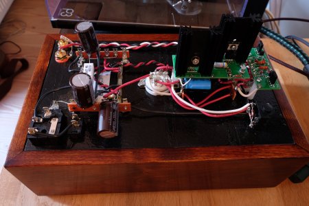
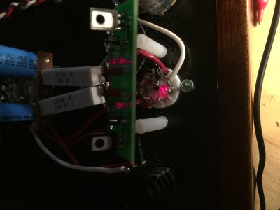
Speedball v1.1 = "Small Circuit Board"
OA= -0.2 to -0.4 (Problem) Expected=60-90v
IA= 179,4(OK) Expected=170-270V
B-A/B= 0V (OK) Expected=0V
IB= 179,4V (OK) Expected=170-270V
OB= 74,4 (OK) Expected=60-90V
"I believe you mean both 22.1K resistors. I will "rollback" the speedball update and report back."
I can unfortunately not do the Speedball rollback because I have just broken one of the 22,4K resistors.

")
")