Speedball install voltage issues [resolved]

Dr. Soot

New member
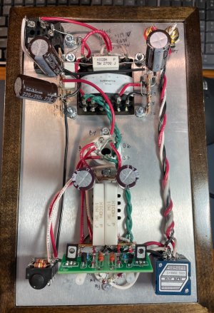
Hi all, I am in the process of installing the Speedball upgrade.  I just finished installing the first board and went through my voltage checks.  Here are the results;
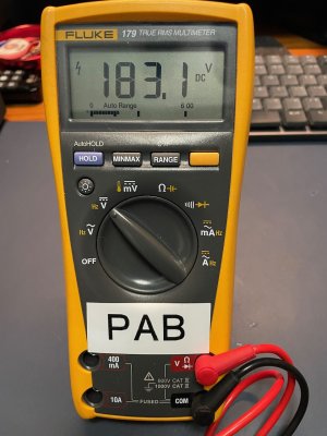
OA -184 V
IA - 185 V
B-A/B - 0 V
IB - 185 V
OB - 184 V

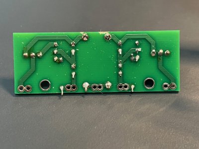
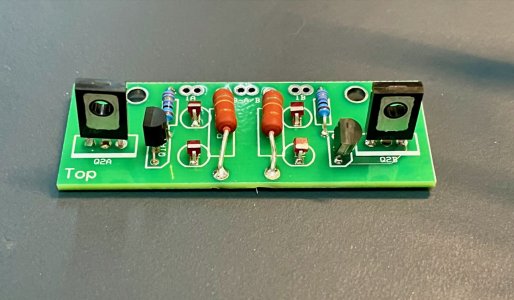
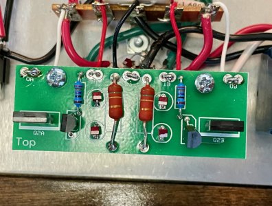
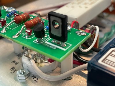
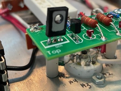
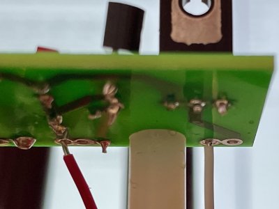
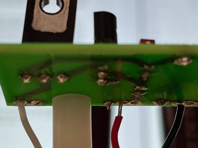
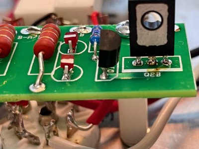
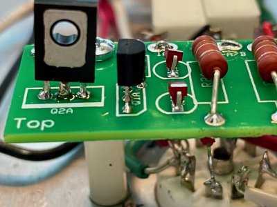
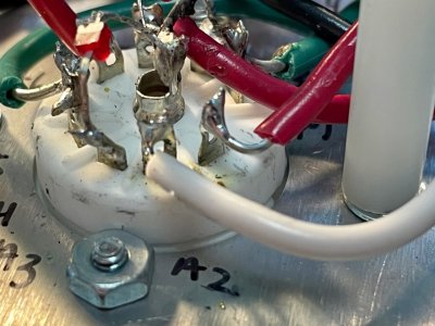
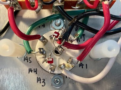
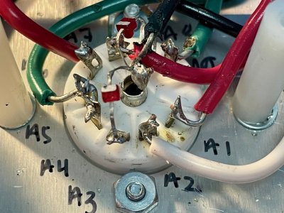
OA and OB should be half of the voltage I am reading.  I followed the flow chart and determined that the 12AU7 does glow, but the LEDs on the bottom of the 9 pin socket do NOT glow.  I went over each of the solder points on the 9 pin socket to make sure they were OK, and they appear to be.

Any help is much appreciated.  Happy to upload some photos, just not sure what to take a photo of.
 
Can you post photos of the top and bottom of the small PC board?

I would expect that you don't have the center legs of the MJE350s well soldered. If your 12AU7 glows, it would be very important to leave the LEDs on the 9 pin socket alone.
 
Here you go.
 

Attachments

  • 1.jpg
    1.jpg
    302.7 KB · Views: 15
  • 2.jpg
    2.jpg
    450.8 KB · Views: 12
  • 3.jpg
    3.jpg
    595.9 KB · Views: 8
  • 4.jpg
    4.jpg
    275.6 KB · Views: 9
  • 5.jpg
    5.jpg
    305.1 KB · Views: 12
Look at the center leg of each MJE350 on the top side of the
PC board photo. There needs to be solder between the leg and the solder pad. Watch this starting at about 36:05  -

https://youtu.be/EN16Pi7pcfk
 
Can you carefully measure the voltages at A3 and A8?  Can you repost the photos of that board?

Also keep in mind that if you try to just add solder from the other side of the board rather than reheating the joints from the bottom, you are unlikely to resolve the issue (I just mention this because we have seen it happen a bunch).
 
A3 = 180.6 V
A8 = 182.2 V
 

Attachments

  • 9.jpg
    9.jpg
    276.2 KB · Views: 6
  • 8.jpg
    8.jpg
    244.3 KB · Views: 4
  • 7.jpg
    7.jpg
    404.1 KB · Views: 5
  • 6.jpg
    6.jpg
    382 KB · Views: 6
A3 and A8 are pins on the 9 pin socket.  You would be the first person in the history of the Crack to measure voltages like that at those pins...

Could you remove that board again and post photos of your stock Crack build without it?
 
ok, here are photos of the 9 pin socket and the stock build


Attachments

  • 14.jpg
    14.jpg
    377.3 KB · Views: 7
  • 12.jpg
    12.jpg
    343.7 KB · Views: 6
  • 11.jpg
    11.jpg
    367.9 KB · Views: 8
  • 10.jpg
    10.jpg
    458.5 KB · Views: 8
  • 10.jpg
    10.jpg
    458.5 KB · Views: 10
Could I see an overhead of the whole build?

A4 and A5 don't look well soldered.

If you have 180V at A3 and A8, then I would be very, very surprised if your stock build functioned properly and passed its original voltage checks.
 
When you say you want to see overhead, you mean right side up?  It worked fine for the last year plus that I have had it.  I will resolder all the pins on the 9 pin socket.
 
I'm interested in seeing the same shot that's on page 46 of the build manual.

If your Crack was functional for that long, please recheck the voltages at terminals A3 and A8.  If they are that high, can you check where the black wires meet at the headphone jack to be sure one isn't loose.
 
here you go

A1 = 184.7 v
A2 = 169.6 V
A3 = 180.9 V
A4 = 0 V
A5 = 0 V
A6 = 184.1 V
A7 = 169.8 V
A8 = 174.5 V
A9 = 0 V

@ the headphone jack

Red = 168.0 V
White = 168.6 V
Black = 169.9 V

Not sure if all of those are helpful, but figured I would add them just in case. 
 

Attachments

  • 15.jpg
    15.jpg
    669.8 KB · Views: 12
Put the 22.1K resistors back and remeasure your voltages.

Are you sure you aren't seeing mV instead of V? 

Which terminal are you using as a ground reference?

When we see a set of voltages like this that are impossible, generally it's a loose, missing, or broken black wire.

Also do be aware that the Alps Blue pot is designed to be installed onto a PC board, and soldering wires directly to those pins will often cause the pins to snap off.  You can buy mounting PC boards for a few bucks on eBay.
 
I cannot find the 22.1K resistors since removing them.  Can you suggest a place for me to purchase them, perhaps the item specs so I can get the correct ones?

I am using 12 as the grounding terminal.

A3 = 183.1 V (see photo)

A8 = 178.4 V (see photo)

Other random voltage measurements

18 = 97 V
20 = 0 V
14 = 0 V
Center of 9 pin socket = 172.4 V

On the pot... (see attached photo for pot labels)
Ground top row = 172.4 V
Ground bottom row = 0 V


Attachments

  • Grounding at position 12.jpg
    Grounding at position 12.jpg
    313.4 KB · Views: 4
  • Voltage at A3.jpg
    Voltage at A3.jpg
    289.5 KB · Views: 8
  • Voltage at A8.jpg
    Voltage at A8.jpg
    280 KB · Views: 2
  • potentiometer.jpg
    potentiometer.jpg
    65.8 KB · Views: 8
The ground lugs on the pot are connected with a piece of wire to terminal 12.  Since you have 180V between those two points, there is a discontinuity in your black ground wire that is causing your amp to not work properly.  As I suggested before, it's extremely common to find this exact issue where the two black wires connect to the headphone jack, and commonly one will not be captured by solder.

From what you are showing, we can be 10000% sure that you have a loose/poorly soldered black wire in your stock build that has nothing to do with the Speedball installation (other than likely being disturbed in the process of fitting that first PC board).

There are only a small handful of solder joints on the ground bus, why not reheat them all?  That would be terminal 3, the junction of the black wires on the HP jack, terminal 12, terminal 14, and terminal 20. 
 
Back
Top