Speedball install voltage issues [resolved]

Thank you for all the help. I finally found the poorly soldered joint on the pot, it was one of the ground wires.  I have since repaired that but was still getting some goofy numbers and started trouble shooting all the solder joints on the 9 pin socket.  I accidentally ended up breaking one of the LEDs (the one at A3) and replaced it with one from the Speedball kit.  That fixed that.  I am still getting about twice the voltage I should be getting at A1 and A6.  I believe it is probably an issue at the pot.  And your suggestion about putting the pot on a breadboard was something I had actually done but for whatever reason, swapped the pot for one without the breadboard.  I have another couple pots, I will put one on a breadboard and go from there.  Again, thank you for all the help.  You guys are awesome.
 
Voltages

1 = 73.9V (seems to have fixed itself or I just mis-measured before)
2 = 0 V
3 = 0 V
4 = 176.7 V
5 = 166.7 V

A1 = 167.6 V
A2 = 0 V
A3 = 1.634 V
A4 = 0 V
A5 = 0 V
A6 = 72.5 V
A7 = 0 V
A8 = 1.576 V
A9 = 0 V

The A3 and A8 LED now glow (they didn't before) but on the Speedball breadboard, only the LED closest to the 1B connection glows.
 
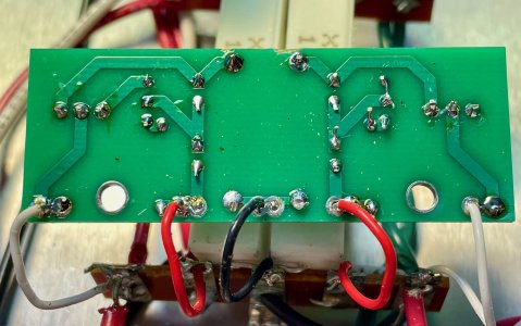
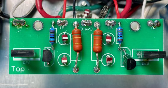
Well half of your Speedball is working at least.  I would expect at least two lit LEDs on the front PC board. The higher than expected voltage at A3 tells us that the half of the C4S feeding A1 is likely attempting to source too much current.  It would be a good idea to see some more photos of the PC board itself, especially the bottom.  You can also remove the wires at IA, OA, IB, and OB, then rotate the board 180 degrees and hook it back up.  If that high voltage moves to terminal 1, then you know you have an issue to deal with on that half of the PC board.

The voltages you posted now show that you do not have the voltage issue you had before.  If you didn't do anything specific to resolve the issue, then you are still going to have to find the loose wire/flaky solder joint causing this issue.

Ultimately I would still suggest finding a pair of 22K/1W resistors just in case, because it's more difficult to debug stock Crack issues once the Speedball is installed.
 
Thanks for the suggestions.  I did resolder the connections on the pot and on the 9 pin, that is when I saw the voltage correction.  I am reasonably confident that solved that issue.  I will do what you suggest on the PC board.  I am sure I just didn't solder well.  I don't have the best vision and even though I use magnifying glasses and whatever else I can use, it still isn't that clear.  I am attaching images of the underside of the PC board.  I may desolder and desolder it all, not sure.  But once again, thank you for all your help.
 

Attachments

  • PC BOARD BOTTOM.jpg
    PC BOARD BOTTOM.jpg
    1.6 MB · Views: 5
  • PC BOARD TOP.jpg
    PC BOARD TOP.jpg
    1.4 MB · Views: 2
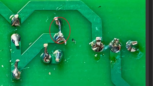
I took care of that solder bridge but have been following all the lines to see check all the connections and currently, I find that OB reads about 10-11 V and I cannot pinpoint the where the voltage drop occurs.  At this point, I am almost re-soldered every connection.  I just may give up and buy a new kit and do it better the second time.  I assume 120 V is coming in and the transformer and at some point, I am getting about 230 V.  I need to check the jumper wire between 14 and 16 on the transformer to make sure it is OK. But I don't think that would explain the voltage drop across the speedball board.  I would assume if I am getting 74 V at at OA and then read about 10.5 V at OB, something must be wrong on the board, not necessarily the crack itself.  Anyway, any chance I can buy a few parts of the speedball and not the whole thing?  Just the one board I have built so far and try again.
 
Leaded solder and more heat will be really helpful.  You can contact replacementparts(at)bottlehead(dot)com regarding purchasing a new front PC board and electronics.
 
I am using Quad Eutectic Solder with rosin core and I have my solder set to 675 F.  Should I use different solder and go hotter?
 
Reheated the solder points on the breadboard at a 800 F and here are my results:

OA - 72.6 V
IO - 181.5 V
B-A/B - 0 V
IB - 181.8 V
OB - 71.9 V

So I think I have got that working well.

I have to wait until the new LEDs come in to finish the second board since I broke one LED earlier.

Also, I put a new Alps Blue volume pot on a small breadboard to clean that up.  Can you please tell me the gauge of the solid core wire used to wire up the volume pot to the headphone jacks?  I'm guessing somewhere between 26-20 gauge, but I want to buy the correct wire.

Thanks again for all your help.

Pedro
 
Back
Top