anthonynchandler
New member
Greetings from the Great North!
I finished my wonderful soldering journey with the Moreplay only to find myself at the dreaded voltage problem on the final page. I thought I would post a cry for help based on my Resistance and Voltage Checks first before posting images, as the numbers may tell more than photos for now.
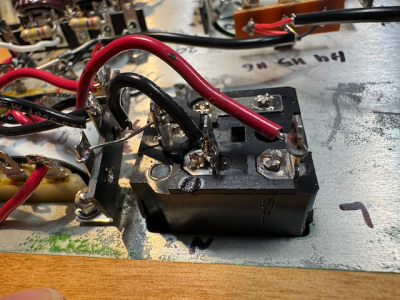
I passed the Power transformer test. I passed the glowing 6v6 test. I passed the Raw B+ voltage test. My numbers for those were spot on.
For the resistance Check the main incongruencies with expectations were:
Terminal 9 - OL
A5 1.94
A6 OL
B5 - 215
B6 - Ranges
Voltage Check DC
Terminal 1. -1.2V
Terminal 4 - 0.1
Terminal 6 - -1.2
Terminal 11 -1.1
Terminal 14 - 0.1
Terminal 16 - -1.1
I should note that I did try the Moreplay in my system (I was not sure if I was just messing up with the multimeter and was off by 1000 or something) and there is nothing. As per my reading of the "rules on p.58 I could proceed with the voltage check. I wore rubber boots and had a hand in my pocket [with Alanis Morissette playing on my phone].
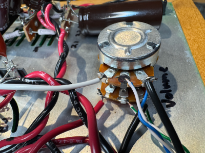
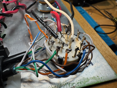
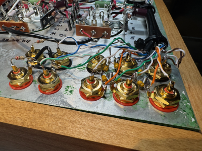
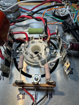
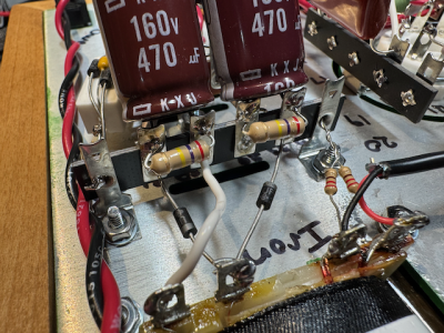
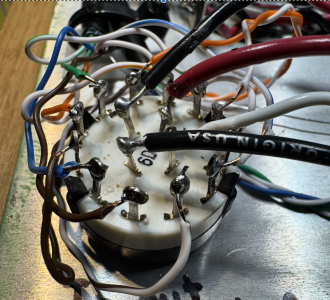
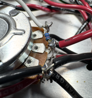
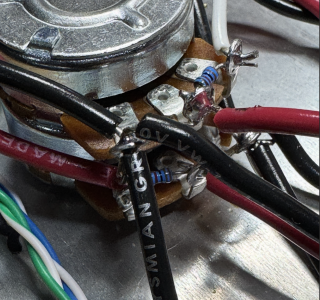
Any thoughts before I go through the entire circuit tomorrow? I thought my solder points were good, and I think my capacitors are in the right directions.
So close...many thanks.
Anthony
I finished my wonderful soldering journey with the Moreplay only to find myself at the dreaded voltage problem on the final page. I thought I would post a cry for help based on my Resistance and Voltage Checks first before posting images, as the numbers may tell more than photos for now.
I passed the Power transformer test. I passed the glowing 6v6 test. I passed the Raw B+ voltage test. My numbers for those were spot on.
For the resistance Check the main incongruencies with expectations were:
Terminal 9 - OL
A5 1.94
A6 OL
B5 - 215
B6 - Ranges
Voltage Check DC
Terminal 1. -1.2V
Terminal 4 - 0.1
Terminal 6 - -1.2
Terminal 11 -1.1
Terminal 14 - 0.1
Terminal 16 - -1.1
I should note that I did try the Moreplay in my system (I was not sure if I was just messing up with the multimeter and was off by 1000 or something) and there is nothing. As per my reading of the "rules on p.58 I could proceed with the voltage check. I wore rubber boots and had a hand in my pocket [with Alanis Morissette playing on my phone].
Any thoughts before I go through the entire circuit tomorrow? I thought my solder points were good, and I think my capacitors are in the right directions.
So close...many thanks.
Anthony