S.E.X. or Crack2A - which is better for learning and experimenting?

  • Thread starter Thread starter Deke609
  • Start date Start date
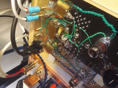
The "Nickel Wonder" is built and it works!

Thanks PB for suggesting it.  I've already learned a lot from the experience ... but about 95% of that was moving things from the "unknown unknowns" column to the "known unknowns" column.  The actual differential circuit still confounds me, but that's ok, at least now I know what I find confusing and it gives me something definite to figure out.

In more practical terms, I learned that layout is H-A-R-D. I failed to take into account all the ground wiring that is involved in "star grounding" when planning the layout; and trying to find a good path for the signal wire away from the transformers is all but impossible!  But I had a lot of fun.  And now I have something to experiment with.  The first thing I want to look at is DC rectification and ripple smoothing -- in no small part b/c it's the only important part of the circuit that I sorta understand.  The Nickel wonder uses 2 diodes to strip out -ve current, but I've seen that many amps use 4 in what I think is called a "bridge" structure.  I might play around with that and additional/different ways of smoothing the DC.  This will give me a reason to learn to use my o-scope. It should be pretty simple to run a sine wave tone through the preamp and actually see the rectification and smoothing -- which will be cool.

Listening wise: I was expecting the Nickel Wonder to sound pretty poor, but it is actually quite listenable when put in front of the S2.  I particularly like what it does to treble -- it seems fuller-bodied and livelier -- but also a lot less detailed. The two observations -- fuller/livelier and less-detailed -- may be related.  I've previously noticed that upgrades/mods that give greater detail often make the sound seem smaller and thinner. The mids of the Nickel Wonder are fine.  But the lower bass is absent.  I have high hopes for the BeePre in front of the S2. 


Attachments

  • Nickel Wonder_resized.jpg
    Nickel Wonder_resized.jpg
    245.9 KB · Views: 14
A bridge rectifier will change the voltage output of the power supply.  Once you blow up an electrolytic capacitor and have to live with that stench, you'll tend to tread fairly carefully on stuff like that in the future! 

One of the features of the differential circuit is that it's less picky about power supply noise. 

This is a powerful tool that you can use to simulate power supplies:
http://www.duncanamps.com/psud2/
One hint that is helpful is that when you use a full wave rectifier in PSUD, the transformer voltage is half the total winding.  In the instance of the Nickel Wonder, you would use a full wave solid state rectifier and the transformer voltage would be 125V. 
 
Paul Birkeland said:
Once you blow up an electrolytic capacitor and have to live with that stench, you'll tend to tread fairly carefully on stuff like that in the future! 

Very good to know! I will start treading carefully now.

And many thanks for the link to PSUD2 and tips.

cheers,

Derek
 
Pick up an old Radio Amateur's Handbook for an approachable discussion of power supply design.
 
Thanks Doc. Amazon sells a new reprint, so I should have a copy of it it a day or so; and it's available electronically for free. The miraculous convenience of modern tech! 

I too remember the days of libraries: go the library, search the catalogue index, copy stack number, go to stack location .. only to find that the book you want has been borrowed by someone else. So you speak to a librarian who tells you that it isn't due back for another 2 weeks. So you put your name on a waiting list and a librarian calls you on your home telephone when it is returned.  All of which seemed reasonably convenient at the time!  Hah!
 
Deke609 said:
It should be pretty simple to run a sine wave tone through the preamp and actually see the rectification and smoothing -- which will be cool.

I just realized that what I wrote above about sending a sine waveform through the amp makes no sense. Signal input doesn't get rectified and no signal passes through the PT (other than 60 HZ AC waveforms). I just need to put scope lead A on the pre-diode output and lead b at various points post-diodes.
 
Back
Top