Then the resistor at A6 would be broken or loose.
You are using an out of date browser. It may not display this or other websites correctly.
You should upgrade or use an alternative browser.
You should upgrade or use an alternative browser.
S.E.X. amp seconde hand
- Thread starter mwgrient
- Start date
would like to check something before:
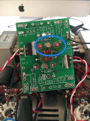
in de manual 2.1 - (the amp is a 2.1 S.E.X. amp) the attachment states something different than my amp. See my picture. Or is this because of the C4S module?
I will take a look at the manual for resitance checks. It looks different on the picture too.
in de manual 2.1 - (the amp is a 2.1 S.E.X. amp) the attachment states something different than my amp. See my picture. Or is this because of the C4S module?
I will take a look at the manual for resitance checks. It looks different on the picture too.
Attachments

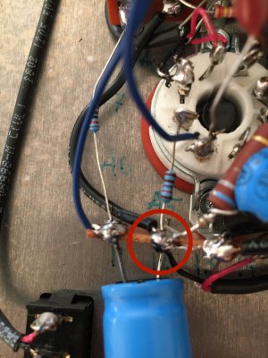
That's the part replaced by the C4S.
") Thank you!
Thank you!Messurements, resistance check.
Terminal - Resistance
1 - *
2 - 0
3 - 0
4 - *
5 - *

6,16 - *


7,17 - 0


8,18 - 0

9,19 - 245

10,20 - *

11,21 - *
1
2,22 - 0

13,23 - 0
14,24 - 093 / 089
15,25 - 890 / 890


A1,B1 - 245 / 245
A2, B2 - *


A3, B3 - 0 / 0
A4,B4 *

A5,B5 - 678 / 678
A6,B6 - 1 / 1
A7,B7 - 6 / 6
A8,B8 6 / 6

C
1,C2,C4,C5 *
What do you think about it?
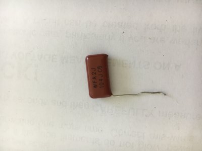
I have to lookup the part/value and buy the resistance online (for a6), like you earlier suggested).
Terminal - Resistance
1 - *
2 - 0
3 - 0
4 - *
5 - *

6,16 - *


7,17 - 0


8,18 - 0

9,19 - 245

10,20 - *

11,21 - *
1
2,22 - 0

13,23 - 0
14,24 - 093 / 089
15,25 - 890 / 890


A1,B1 - 245 / 245
A2, B2 - *


A3, B3 - 0 / 0
A4,B4 *

A5,B5 - 678 / 678
A6,B6 - 1 / 1
A7,B7 - 6 / 6
A8,B8 6 / 6

C
1,C2,C4,C5 *
What do you think about it?
I have to lookup the part/value and buy the resistance online (for a6), like you earlier suggested).
Those resistances look like maybe the meter isn't on a range that will adequately resolve the resistor values all that well. You can use your meter to measure the 1.27K resistor, does it measure 1.27K?
The idea that you need to run out and buy new parts to replace all the parts in your SEX amp will create more problems than it will solve. It's important to figure out what's actually not working, then fix that. If you make guesses and start replacing parts at random, you will very likely make more operational problems than you had before.
The idea that you need to run out and buy new parts to replace all the parts in your SEX amp will create more problems than it will solve. It's important to figure out what's actually not working, then fix that. If you make guesses and start replacing parts at random, you will very likely make more operational problems than you had before.
OK, so there's no need to replace a resistor that reads the proper resistance.
You had 0V across this part, then 9V across this part. This is indicative of loose parts or a broken wire in the amp.
You had 0V across this part, then 9V across this part. This is indicative of loose parts or a broken wire in the amp.
Yes, it's an indication that you have a broken wire or a loose connection on that side of the amp.
That part can be 100% out of the circuit and the DC voltages will still be correct.
I would like to share the measurements again, I have a different multimeter:
Terminal - Voltage
1 - 201
2 - 0
3 - 0
4 - 403
5 - 201
6,16 - 379 / 383
7,17 - 0 / 0
8,18 - 0 / 0
9,19 - 0 / 0
10,20 - 403 / 404
11,21 - 300 / 347
12,22 - 0 / 0
13,23 - 0 / 0
14/24 - 0 / 0
15,25 - 17 / 17
A1,B1 - 0 / 0
A2,B2 - 361 / 357
A3,B3 - 17 / 17
A4,B4 - 0 / 0
A5,B5 - 295 / 66
A6,B6 - 9 / 2
A7,B7 - 2 / 2
A8,B8 - 3 / 3
C1 - 2
C2 - 3
C3 - 0
C4 - 3
C5 - 3
I can use any input since I really totally lost here. I have a focus on the right channel, special interest in A5/A6 because of te big differences.
As Paul said, loose wire or broken wire; anything? I have re-soldered all the joints on te right. I Gould replace all the wiring on the right side; but have been warned not to do more dan necessary.
I have tubes glowing; but no right channel. I spend all day thinking and wondering... but need a little push.
The other thing that could make 9V across the 1.27K resistor would be if A4 isn't properly grounded. A4 grounds through the 249K resistor, if that's not well connected or is broken, that will throw everything off.
Paul Birkeland said:That part can be 100% out of the circuit and the DC voltages will still be correct.
But will effect the sound from that channel? I have removed them all (2); now there's no sound at all. Right or Left. I understand that these resistors are responsible for eliminating noise?
Similar threads
- Replies
- 4
- Views
- 134
- Replies
- 9
- Views
- 298
- Replies
- 5
- Views
- 3K