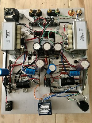
I finished my SEX 3.0 but had a dead right channel so decided to resolder everything on the A side and changed the pot to an Alps 100k. Now, every resistance on the B side is wrong, everything reads OL. I didn't touch anything on this side and the soldering seems OK. Any help is appreciated!
You are using an out of date browser. It may not display this or other websites correctly.
You should upgrade or use an alternative browser.
You should upgrade or use an alternative browser.
Resistance issue [resolved]
- Thread starter soundfel
- Start date
B15 bolts to the chassis, is that 0 ohms?
For the rest of the terminals that should read 0 ohms on the b side, there's a buss of black wires that bounces between the terminal strips and terminates back at the high voltage power supply. One of those wires has to be loose or missing for you to be betting OL on terminals that should otherwise be 0.
For the rest of the terminals that should read 0 ohms on the b side, there's a buss of black wires that bounces between the terminal strips and terminates back at the high voltage power supply. One of those wires has to be loose or missing for you to be betting OL on terminals that should otherwise be 0.
Why did you rewire the A1/A12 cable? What did you replace it with?
Thermioniclife
Member
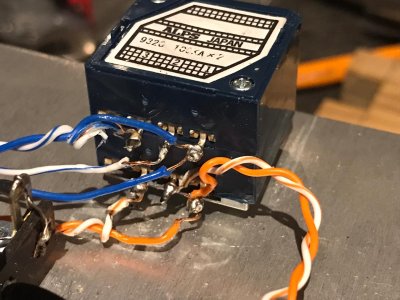
Maybe its just the angle of the photo but I do not see anything connected to the wiper of the alps pot (pin 2)
This is what feeds the voltage amplifier grid of the 6fj7 pin 10 on that tube.
This is what feeds the voltage amplifier grid of the 6fj7 pin 10 on that tube.
Thermioniclife
Member
Without a grid load your going to have big problems. this load comes from the pot in this instance.
Thermioniclife
Member
I'm sure you can use the Alps pot but I feel that the circuit may be miss wired. please check that the wiper of the pot is soldered to pin 8
of the 6fj7 socket and the grid stop resistor. then make sure the grid stopper resistor is connected to pin 10 of that socket.
pin 8 is an unused pin for that tube that makes it a convenient mounting place to mount the grid stopper resistor. Having said that I still feel that perhaps your volume pot may be miss wired so perhaps a few more photos of the pot showing the connections to the pins could be useful.
Now that the resistances are OK, how are the voltages?
Hello, Paul. Not looking good... I´m getting around 485v on terminals 2, 6, 7, 10, 13, 16, 20, 21, 24 and 27. The rest of the terminals on that section are 0v. On terminal 20 I get 20v, 487v on 33, 243v on 34 and 35 and 0v on 29, 31,32 and 36. It marks around 22v on H2, H3, H5 and H6, and 0v on the rest.
Did you pass the glow test?
Well, if you don't pass the glow test, none of those DC voltages will be correct. So neither tube glows? When you replaced that STP cabling, you disabled the heaters. This is the wiring that feeds pins 1 and 12 on each 12 pin socket. Follow that backwards and you'll be at the 10,000uF cap and 0.1 ohm resistor, then backwards from there you get to the H terminal strip with the big rectifier diodes that mount to the chassis.
Something is not connected or broken along that path. You can forget about doing any other debugging of any kind until your amp passes the glow test again.
Something is not connected or broken along that path. You can forget about doing any other debugging of any kind until your amp passes the glow test again.
Both tubes are off. All the wiring looks fine. I replaced the wires that run 31/32 and resoldered but still no glow. Since I'm getting no voltage at H4, could it be a problem with the power transformer? I ran the transformer secondary test on the manual again and it's OK, the AC voltage are also normal. Do you think I should replace the capacitor or the 0.1 resistor?
I think you should stop replacing parts without actually knowing they are bad. You had glowing tubes, now you don't. All that you've changed is the STP wiring that heats the tubes. If the capacitor is bad, it will pop its top and blow out its goo, and you would be telling me about that. The primary way that happens is if you install it backwards. You wouldn't have ever passed the glow test if you had put that cap in backwards. Likewise I couldn't figure out a way that you could kill the 0.1 ohm resistor. If you start pulling these parts out and replacing them without any reason to do so, you will continue to make new problems that you will have to track down.
With one probe on H2 and the other probe on H4, what DC voltage do you get? How about with one probe on H5 and the other probe on H7?
With one probe on H2 and the other probe on H4, what DC voltage do you get? How about with one probe on H5 and the other probe on H7?
Similar threads
- Replies
- 3
- Views
- 2K
- Replies
- 13
- Views
- 3K
- Replies
- 9
- Views
- 5K