Motordiesel
New member
Good evening,
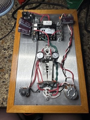
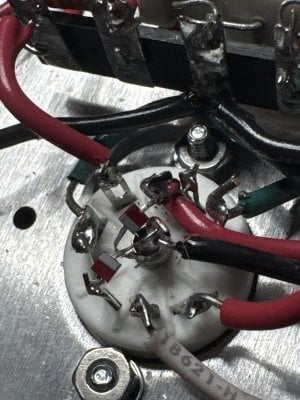
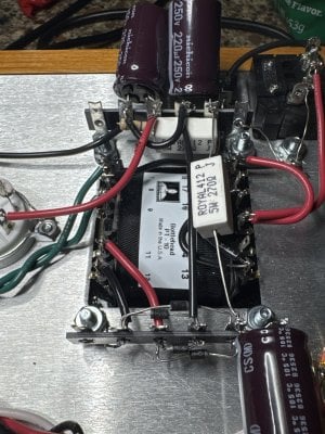
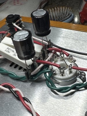
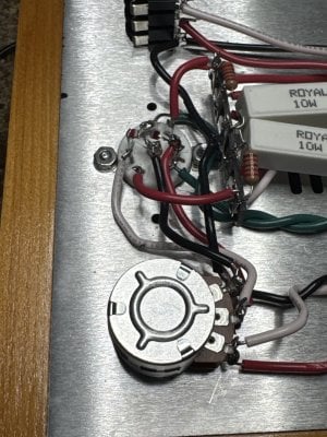
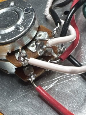
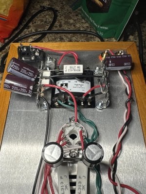
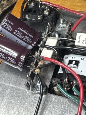
I’m new to building amps and just completed my first Bottlehead Crack OTL. I got to the resistance checks a week ago and on some if the terminals with asterisks I got OL on my Klein MM600. Being that they were not 0 as stated they shouldn't be in the manual, I thought this was ok. when I fired up my amp to do the the voltage checks, the fuse blew. I traced back thru my connections and found the 2-3/4" red wire between the middle terminal on the lower deck of the volume pot and A7 had melted onto A9 right through the casing on the wire. this is what I assume caused the fuse to blow. what did you guys get for ohm ranges for the terminals with asterisks beside them? :
1
2
4
5
13