You are using an out of date browser. It may not display this or other websites correctly.
You should upgrade or use an alternative browser.
You should upgrade or use an alternative browser.
Resistance Check Failure [solved]
- Thread starter Rhok
- Start date
New results:
Max range set to 400
1: - 000.6 vDC
2: - 000.6 vDC
3: 0 vDC
4: - 000.6 vDC
5: - 000.6 vDC
6: 0 vDC
7: 0 vDC
8: 0 vDC
9: 0 vDC
10: 0 vDC
11: 0 vDC
12: 0 vDC
13: - 000.6 vDC
14: 0 vDC
15: - 000.6 vDC
20: 0 vDC
21: - 000.6 vDC
A1: - 000.6 vDC
A2: 0 vDC
A4: 0 vDC
A5: 0 vDC
A6: - 000.6 vDC
A7: 0 vDC
A9: 0 vDC
B1: - 000.6 vDC
B2: - 000.6 vDC
B3: 0 vDC
B4: - 000.6 vDC
B5: - 000.6 vDC
B6: 0 vDC
B7: 0 vDC
B8: 0 vDC
And on auto range:
1: - 0.679 vDC
2: - 0.680 vDC
3: 0 vDC
4: - 0.682 vDC
5: - 0.684 vDC
6: 0 vDC
7: 0.012 vDC
8: 0 vDC
9: 0.014 vDC
10: 0 vDC
11: 0 vDC
12: 0 vDC
13: - 0.665 vDC
14: 0 vDC
15: - 0.663 vDC
20: 0 vDC
21: - 0.661 vDC
A1: - 0.666 vDC
A2: 0 vDC
A4: 0 vDC
A5: 0 vDC
A6: - 0.665 vDC
A7: 0 vDC
A9: - 0.001 vDC
B1: - 0.664 vDC
B2: - 0.662 vDC
B3: 0.011 vDC
B4: - 0.663 vDC
B5: - 0.660 vDC
B6: 0.013 vDC
B7: 0.007 vDC
Grainger49
New member
I guess I'll state the obvious, something is wrong. If the tubes glow you should have about 6.3V AC on the heaters. You have nothing anywhere.
I'll assume that your measuring method is the problem. Voltage is read from one point to another. And depending on the reference it can change.
Get some jumpers, wire with an alligator clip on each end, from Radio Shack. Take a jumper and attach one end to the black lead of your meter. Attach the other end to terminal 3 or one of the resistor leads that are soldered to terminal 3. The resistor leads are easy to clip to.
Set your meter to AC volts and auto ranging, that is usually pretty good. Turn on your Crack and carefully use the red lead to read the voltage at the small tube socket pin 4, then pin 9. One of those should give a reading close to 6.3V AC.
Hello Grainger,
Thanks for your input, this actually was how I was already making my readings - my multimeter has different leads, one of which is an alligator clip.
When measuring AC voltage, I do get readings - and when I switch to DC I get the readings I posted.
A4: 14.3 m V AC
A9: 06.14 V AC
I would definitely agree I am doing something wrong, or have the build wrong, but I am not quite sure of what that is. I'm really new to these kind of projects, and I really appreciate the provided assistance and patience with my situation.
OK, set your meter to AC volts at its highest range and measure the voltage across power transformer terminals 6 and 7, and then measure across power transformer terminals 9 and 10. These are the terminals right on the power transformer, not the strips mounted to the chassis. For each pair of terminals it doesn't matter which test lead goes to which terminal, as you are measuring AC volts. You should see roughly 150VAC across either pair. If that checks out OK we will proceed to the rectifiers.
Grainger49
New member
Ok, those are good readings.
Try this, put one meter lead on transformer terminal 9 and one on transformer terminal 10. It is still AC. It should be about 150V AC but will probably be higher since it doesn't seem to be turning on the tubes yet.
And I see I was too slow, someone else posted that already.
Try this, put one meter lead on transformer terminal 9 and one on transformer terminal 10. It is still AC. It should be about 150V AC but will probably be higher since it doesn't seem to be turning on the tubes yet.
And I see I was too slow, someone else posted that already.
OK, this is a bit of a pain, but try disconnecting the 270 ohm resistor and the positive terminal of the 220 uF capacitor from terminal 21 and then measure the DC voltage at terminal 21 the same way as before, red to 21, black to 12. That will help determine if the rectifiers are bad, or if they are working Ok and there is a short to ground in the circuit somewhere after the rectifiers.
By the way, I have had meters that worked OK on lower scales but didn't work on the highest voltage scale. If you had it set to a lower scale when you checked the battery you might want to measure that battery one more time on the 400V scale. It won't be as accurate, but you should see at least 1V.
By the way, I have had meters that worked OK on lower scales but didn't work on the highest voltage scale. If you had it set to a lower scale when you checked the battery you might want to measure that battery one more time on the 400V scale. It won't be as accurate, but you should see at least 1V.
Grainger49
New member
How about posting a picture of the right and left sides of the terminal strip where the diodes are. We want to verify that the diodes are oriented properly.
Doc, I will attempt your recommendation after Grainger reviews my pictures, additionally, while having my multimeter set to 400 range, testing the same battery yielded these results: 001.3 V DC.
Grainger, here are the pictures you requested: http://i752.photobucket.com/albums/xx165/mikemathis3/IMG_0719_zps273125bf.jpg & http://i752.photobucket.com/albums/xx165/mikemathis3/IMG_0718_zps0b94f959.jpg
Grainger, here are the pictures you requested: http://i752.photobucket.com/albums/xx165/mikemathis3/IMG_0719_zps273125bf.jpg & http://i752.photobucket.com/albums/xx165/mikemathis3/IMG_0718_zps0b94f959.jpg
Grainger49
New member
They are all correct. I also see the caps are oriented properly.
I'm with Dan, try reading the DC as he says and then directly. Try measuring DC from (always the black lead) terminal 21 to (always the red lead) terminal 20.
Also, I'm not positive that the AC feed is solid. Try measuring from terminal 18 to terminal 19.
Your transformer seems to work properly. The circuit just totally dead somewhere and we are right on top of it. It will come to light soon. Hang in there.
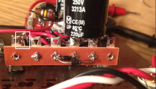
You're the freaking man Paul! Excellent attention to detail, it was just making connection with the insulation instead of the wire. As soon as I saw what you saw I removed the solder from that terminal, readjusted the wires, and re soldered, we may be in business now I'm going to do another voltage check.
21: 205.5 V DC
Additionally - LEDs glow!
Will post more momentarily.
21: 205.5 V DC
Additionally - LEDs glow!
Will post more momentarily.
New results:
1: 080.8 vDC
2: 165 vDC
3: 0 vDC
4: 165 vDC
5: 078.5 vDC
6: 0 vDC
7: 100.8 vDC
8: 0 vDC
9: 100.4 vDC
10: 0 vDC
11: 0 vDC
12: 0 vDC
13: 165 vDC
14: 0 vDC
15: 185 vDC
20: 0 vDC
21: 206.5 vDC
A1: 078.4 vDC
A2: 0 vDC
A4: 0 vDC
A5: 0 vDC
A6: 080.4 vDC
A7: 0 vDC
A9: 0 vDC
B1: 079.9 vDC
B2: 164.8 vDC
B3: 100.6 vDC
B4: 078.5 vDC
B5: 165.1 vDC
B6: 101.4 vDC
B7: 0 vDC
B8: 0 vDC
Alright guys, it doesnt look like we're in the clear just yet - I tested the amp with a cheap pair of headphones I did receive audio (awesome! and thank you for getting me that far!) however, I'm not receiving any output from the right channel.
EDIT:
I've also took some additional pictures: http://s752.photobucket.com/user/mikemathis3/library/xx
EDIT:
I've also took some additional pictures: http://s752.photobucket.com/user/mikemathis3/library/xx
Strikkflypilot
New member
Maybe a longshot but tried to swap inputs?
Similar threads
- Replies
- 3
- Views
- 163
- Replies
- 5
- Views
- 3K
- Replies
- 6
- Views
- 14K